Retinal flux density meter and method of use

a flux density and meter technology, applied in the field of illumination meters, can solve the problems of inability to readily accept illuminance measurements, inability to accurately measure radiometric instruments, and expensive and impractical radiometric instruments

Active Publication Date: 2007-08-21
RENESSELAER POLYTECHNIC INST
View PDF6 Cites 6 Cited by
  • Summary
  • Abstract
  • Description
  • Claims
  • Application Information

AI Technical Summary

Problems solved by technology

Radiometric measurements are rarely made outside sophisticated laboratories, however, because accurate radiometric instruments are expensive and impractical for field measurements.
Lighting practitioners have not readily accepted illuminance measurements based upon Vλ, however, a

Method used


Image

  • Retinal flux density meter and method of use
  • Retinal flux density meter and method of use
  • Retinal flux density meter and method of use

Examples


Embodiment Construction

[0077]The invention described below is a meter that approximates retinal flux density. That is, it approximates the density of light falling on the retina of an eye. In an exemplary embodiment, the meter may be made small enough to be easily portable.

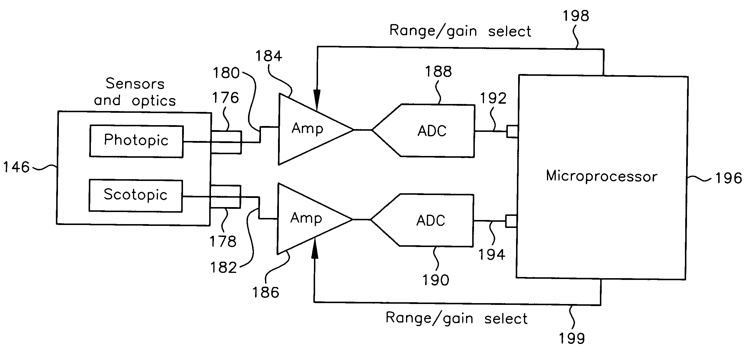
[0078]A schematic diagram of retinal flux density (RFD) meter 146 is shown in FIG. 11A. The RFD meter 146 shown in FIG. 11A includes a cylindrical housing 148, a cylindrical baffle 150, a lens 152, a decentered aperture 154, an optical diffuser 160, a beam splitter 161, a photopic filter 169, a scotopic filter 162, and two silicon photodiodes or other photocells 164, 170.

[0079]Photopic filter 169 and scotopic filter 162 may be coupled to their own photocells 170 and 164, respectively. In an exemplary embodiment, photocell 164 may be behind filter 162 and photocell 170 may be behind filter 169. In an alternative embodiment, photocells may be developed that have the same response curves as those provided by filters 162 and 169. In that al...


PUM


Abstract

A system for approximating flux density of light on a human retina. A housing has an opening allowing light to pass to inside the housing. A baffle coupled to the housing replicates a facial cutoff function response for the light inside the housing. Two detectors are positioned to detect the light inside the housing. One detector produces a photopic spectral response function of the light inside the housing that approximately replicates a spectral response of the foveal cones in the retina. Another detector produces a scotopic spectral response function of the light inside the housing that approximately replicates a spectral response of rods in the retina. A processor coupled to the detectors calculates a mesopic flux density of the light inside the housing based on the photopic and scotopic spectral response functions.

Description

CROSS REFERENCE TO RELATED APPLICATIONS[0001]This application claims the benefit of priority to U.S. Provisional Patent Application Ser. No. 60 / 450,546, filed on Feb. 27, 2003, the contents of which are incorporated in this application by reference.FIELD OF THE INVENTION[0002]The present invention relates generally to an illuminance meter and, more particularly, to a retinal flux density meter; that is, an illuminance meter that can approximate flux density on the human retina using both photopic and scotopic spectral responses.BACKGROUND OF THE INVENTION[0003]Illuminance is the amount of light that falls onto a given area. For example, it is the amount of light that falls per square millimeter. Luminance is the amount of light that is emitted from a given area from a given angle. Luminance has a directional component to it. Luminance is most closely related to brightness and most closely related to what a person sees. Flux density is a measure of illuminance.[0004]Radiometry is the...

Claims


Application Information

Patent Timeline
IPC IPC(8): A61B3/10A61B3/00A61B3/02H05B41/00A61B3/06A61B3/12
CPCA61B3/06A61B3/12
Inventor VAN DERLOFSKE, JOHNREA, MARKBULLOUGH, JOHNBIERMAN, ANDREW
Owner RENESSELAER POLYTECHNIC INST
Why Eureka
Try Eureka