Integral ballast lamp thermal management method and apparatus

a ballast lamp and integrated technology, applied in lighting and heating apparatus, lighting apparatus, vehicle components, etc., can solve the problems of overheating of components, damage to integral electronics lamps, and various other lamps and lighting systems also suffer from heat control problems

Inactive Publication Date: 2007-08-21
GENERAL ELECTRIC CO
View PDF31 Cites 85 Cited by
  • Summary
  • Abstract
  • Description
  • Claims
  • Application Information

AI Technical Summary

Problems solved by technology

Both the light source and the various electronics generate heat, which can exceed the component's temperature limits and damage the in

Method used


Image

  • Integral ballast lamp thermal management method and apparatus
  • Integral ballast lamp thermal management method and apparatus
  • Integral ballast lamp thermal management method and apparatus

Examples


Embodiment Construction

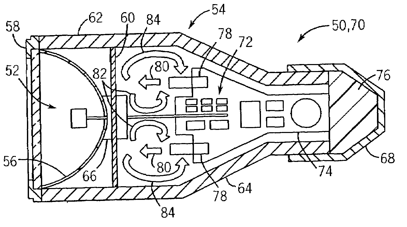
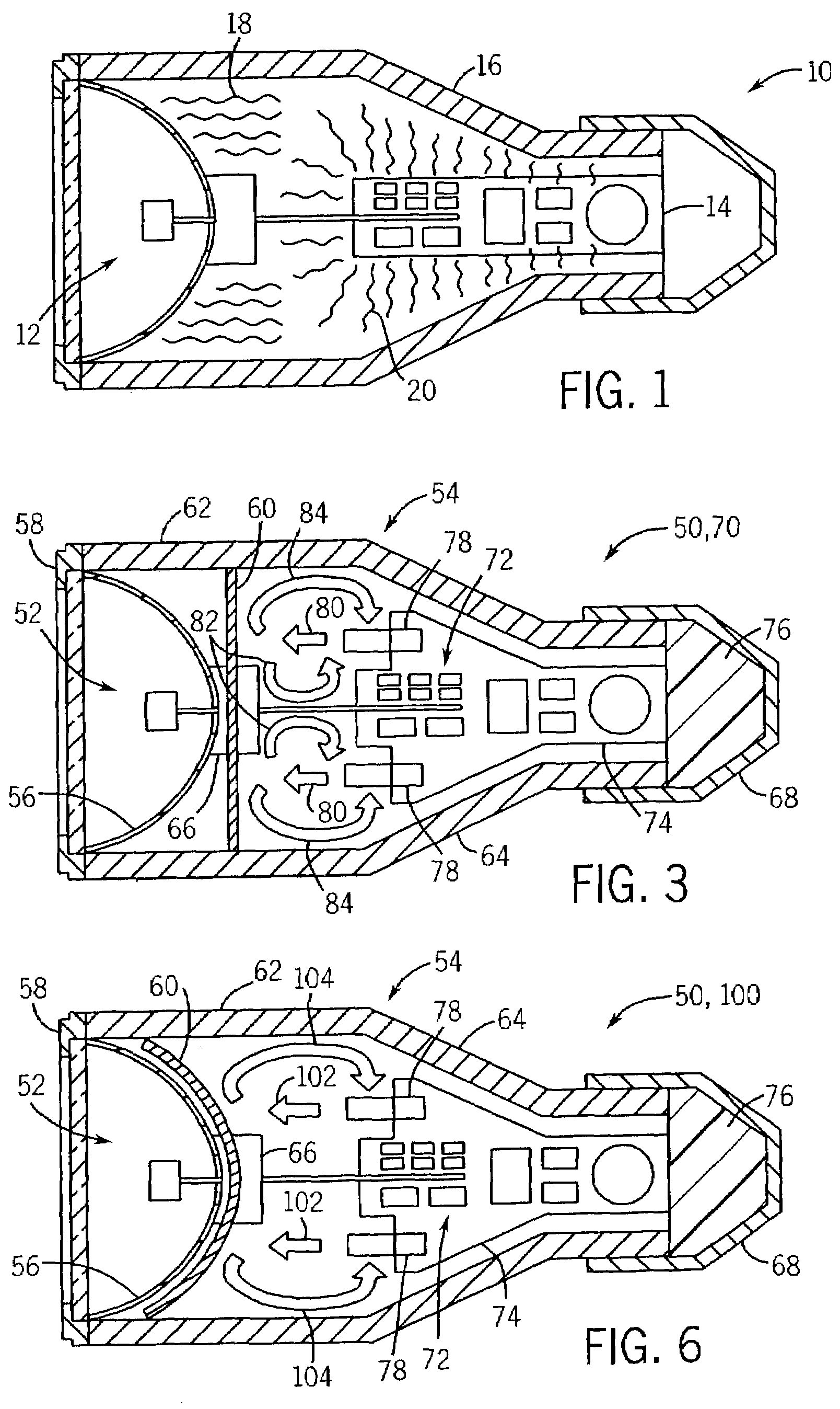
[0015]As noted above, lighting systems often have undesirable thermal gradients and other heating problems, which affect the performance, longevity, and operability of the lamp and the integral electronics. FIG. 1 illustrates typical heating characteristics in a lamp 10, which has a light source 12 and electronics 14 disposed within a closed housing 16. As illustrated, the lamp 10 generates heat 18 from the light source 12 and heat 20 from the electronics 14. The present technique provides a unique thermal distribution mechanism, which is particularly well-suited for distributing the heat 18 and 20 to provide a desired heat profile in the lamp 10. As described in detail below, the thermal distribution mechanism may comprise a variety of insulative, radiative, convective, and conductive thermal transfer mechanisms inside and outside of the closed housing 16. Although the thermal distribution mechanism may be used with any type or configuration of lighting systems, various aspects of ...


PUM


Abstract

A lamp having a lighting source, integral electronics, and a thermal distribution mechanism disposed in a housing. The thermal distribution mechanism may include a For example, the lamp may include a thermal shield between the lighting source and the integral electronics. The lamp also may have a forced convection mechanism, such as an air-moving device, disposed adjacent the integral electronics. A heat pipe, a heat sink, or another conductive heat transfer member also may be disposed in thermal communication with one or more of the integral electronics. For example, the integral electronics may be mounted to a thermally conductive board. The housing itself also may be thermally conductive to conductively spread the heat and convect/radiate the heat away from the lamp.

Description

BACKGROUND OF THE INVENTION[0001]The present technique relates generally to the field of lighting systems and, more particularly, to heat control in lamps having integral electronics. Specifically, a lamp is provided with a heat distribution mechanism, which may comprise a thermal shield, a heat pipe, a heat sink, an air-moving device, and thermally conductive members.[0002]Lighting companies have begun to develop integral electronics lamps in response to emerging market needs and trends. These integral electronics lamps generally comprises a light source and a plurality of integral electronics, such as MOSFETs, rectifiers, magnetics, and capacitors. Both the light source and the various electronics generate heat, which can exceed the component's temperature limits and damage the integral electronics lamp. In many of these integral electronics lamps, the light source and the integral electronics are disposed in a fixture, which further restricts airflow and reduces heat transfer awa...

Claims


Application Information

Patent Timeline
IPC IPC(8): F21V29/00F21V29/02F21V29/15
CPCF21V29/004F21V29/15F21V29/02F21V29/006F21V29/51F21V29/67F21V29/70
Inventor MORRIS, GARRON K.MUNDRA, KAMLESHSTEVANOVIC, LJUBISA DRAGOLJUBJOSHI, ASHUTOSHROUAUD, DIDIER G.SARKOZI, JANOS G.
Owner GENERAL ELECTRIC CO
Why Eureka
Try Eureka