Dielectrophoretic displays

a display and dielectrophoretic technology, applied in the field of dielectrophoretic displays, can solve the problems of long image quality, inadequate service life of the display, and limited color range of each pixel of the display

Inactive Publication Date: 2007-08-21
E INK CORPORATION
View PDF152 Cites 553 Cited by
  • Summary
  • Abstract
  • Description
  • Claims
  • Application Information

AI Technical Summary

Benefits of technology

[0028]applying an electric field of a polarity opposite to the first polarity to the cavity, thereby causing the second type of particles to approach the viewing surface and the cavity to display the second optical characteristic at the viewing surface.

Problems solved by technology

Such unencapsulated displays typically have problems with their long-term image quality which have prevented their widespread usage.
For example, particles that make up such electrophoretic displays tend to cluster and settle, resulting in inadequate service-life for these displays.
One of the problems with electrophoretic displays is the limited range of colors which each pixel of the display can produce.
Again, this type of medium is only capable of producing two colors at each pixel, namely the colors of the two types of particles.
The main problem with this approach to generating color is that the brightness of the display is limited by the pixelation of the color filter.
For example, if a red color is desired, the pixels covered by red filters are set to appear red. whereas the pixels covered by green and blue filters are set to appear dark, so that only a fraction of the display surface has the desired color while the remaining portion is dark, thus limiting the brightness of any color obtained.
However, it is known that objects can be moved by dielectrophoretic forces, that is to say that dipoles induced in the objects by a non-uniform electric field cause the particles to move towards regions of higher field strength.
However, since the movement involved is that of a bubble against a contrasting background, such an apparatus does not appear capable of displaying an arbitrary image.

Method used


Image

  • Dielectrophoretic displays
  • Dielectrophoretic displays
  • Dielectrophoretic displays

Examples


Embodiment Construction

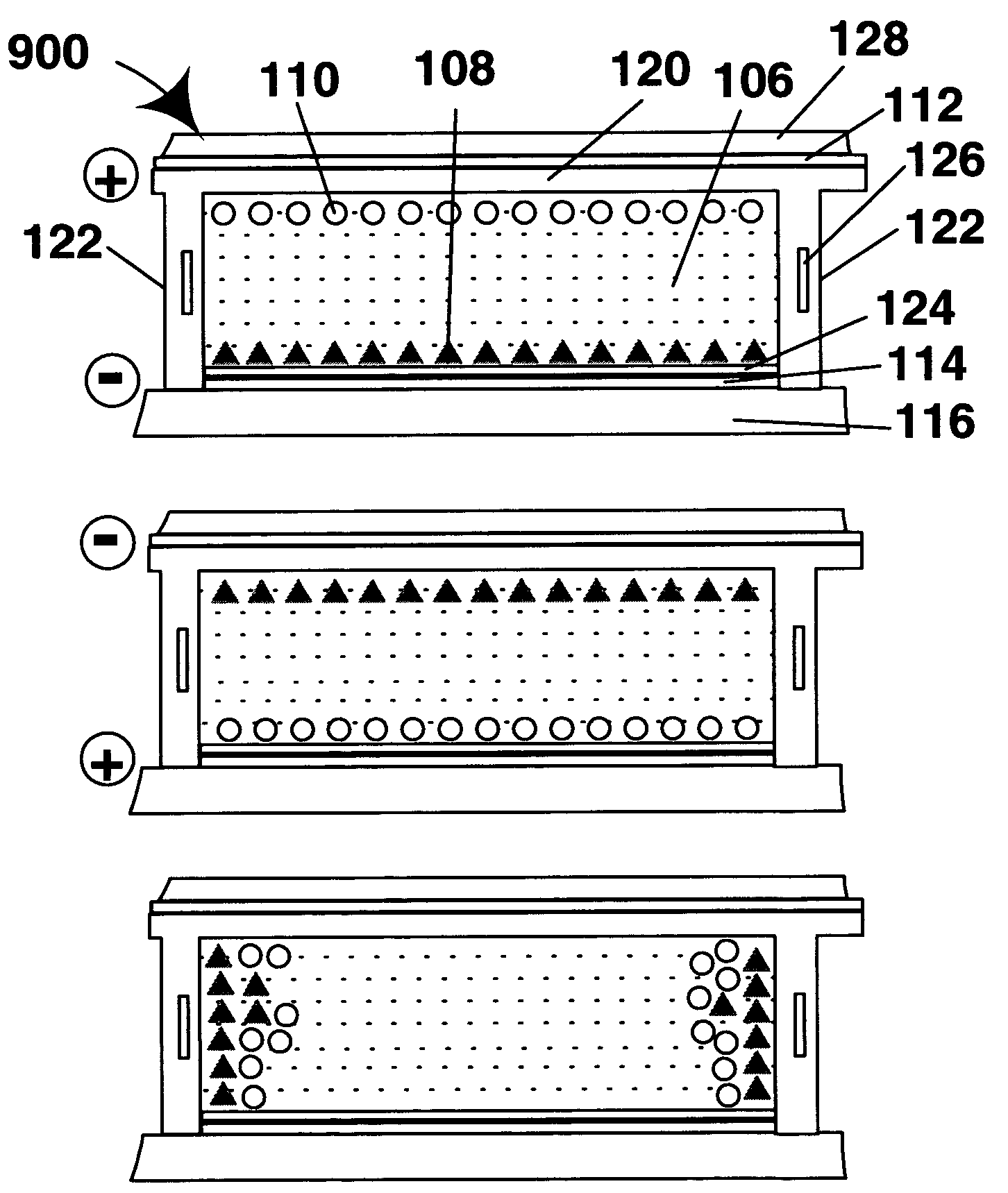
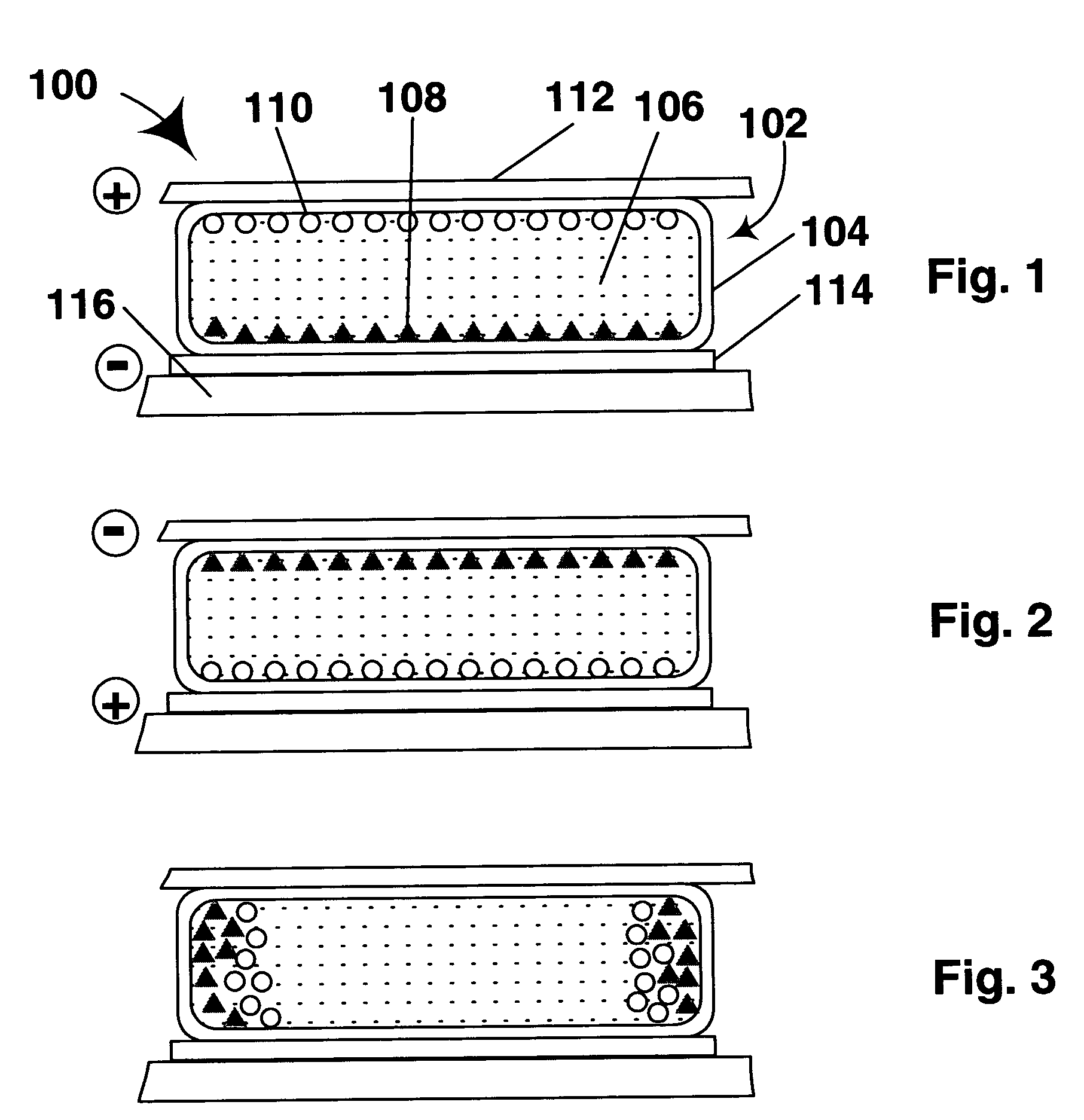
[0036]As already mentioned, this invention provides a dielectrophoretic display comprising a substrate having walls defining at least one cavity, the cavity having a viewing surface and a side wall inclined to the viewing surface; a suspending fluid contained within the cavity; a plurality of at least one type of particle suspended within the suspending fluid; and means for applying to the substrate an electric field effective to cause dielectrophoretic movement of the particles to the side wall of the cavity.

[0037]References to “viewing surface” and “side wall” herein do not imply that these surfaces are perpendicular to each other, though a substantially perpendicular arrangement of the two surfaces is preferred, since when the particles are disposed adjacent the side wall of the cavity, such a perpendicular arrangement minimizes the area of the viewing surface occupied by the particles, and hence permits the maximum amount of light to pass through the cavity. The side wall or wal...


PUM

PropertyMeasurementUnit
frequencyaaaaaaaaaa
electrophoretic mobilityaaaaaaaaaa
optical characteristicaaaaaaaaaa

Abstract

A dielectrophoretic display comprises a substrate having walls defining at least one cavity, the cavity having a viewing surface and a side wall inclined to the viewing surface; a suspending fluid contained within the cavity; a plurality of at least one type of particle suspended within the suspending fluid; and means for applying to the substrate an electric field effect effective to cause dielectrophoretic movement of the particles to the side wall of the cavity.

Description

CROSS REFERENCE TO RELATED APPLICATIONS[0001]This application is a non-provisional of Provisional Application Ser. No. 60 / 419,019, filed Oct. 16, 2002. This application is also a continuation-in-part of application Ser. No. 08 / 983,404, filed Mar. 26, 1999 now U.S. Pat. No. 7,106,296, which is the United States National Phase of International Application No. PCT / US96 / 12000, filed Jul. 19, 1996, which is itself a continuation-in-part of application Ser. No. 08 / 504,896, filed Jul. 20, 1995 (now U.S. Pat. No. 6,124,851). The entire disclosure of all the aforementioned applications, and of all U.S. patents and published applications mentioned below, is herein incorporated by reference.BACKGROUND OF INVENTION[0002]This invention relates to dielectrophoretic displays, and methods for operating such displays. More specifically, this invention relates to dielectrophoretic displays in which solid particles and a suspending fluid are held within a cavity.[0003]Electrophoretic displays have bee...

Claims


Application Information

Patent Timeline
Patent Type & Authority Patents(United States)
IPC IPC(8): G09G3/34G02B26/02G02F1/166G02F1/16762G04G21/04G06F15/02G09G3/20G09G3/30G09G3/36G09G3/38H01L27/28H01L51/00H01L51/05H01L51/30
CPCB41J2/01B41J2/02B41J3/4076B82Y10/00B82Y20/00C09D11/30C09D11/50G02B26/026G02F1/1334G02F1/1343G02F1/134309G02F1/1345G02F1/135G02F1/167G02F1/172G04B47/00G06F15/0283G06K19/07703G09F9/302G09F9/372G09G3/344H01L27/12H01L27/28G02F1/133305G02F1/133348G02F1/13336G02F1/13439G02F1/1365G02F1/19G02F2001/1676G02F2202/12G02F2202/28G09G3/38G09G2310/0267G09G2310/0275G09G2380/02H01L51/0036H01L51/0038H01L51/0045H01L51/005H01L51/0051H01L51/0052H01L51/0077H01L51/0078H01L51/0508H01L51/0512H05K1/097H05K3/105H05K3/1241G02F1/166G02F1/16762G09G3/035H10K19/00H10K85/114H10K85/20H10K85/113H10K85/60H10K85/611H10K85/615H10K85/30H10K85/311H10K10/46H10K10/462
Inventor ARANGO, ALEXI C.JACOBSON, JOSEPH M.
Owner E INK CORPORATION
Why Eureka
Try Eureka