
Fixing apparatus

a fixing apparatus and fixing plate technology, applied in the direction of electrographic process apparatus, instruments, optics, etc., can solve the problems of not being properly delivered to the delivery tray, the risk of producing a large curl on the sheet of paper coming out of the fixing apparatus, and other problems, so as to reduce the curl of the image forming medium

Active Publication Date: 2007-08-21
KK TOSHIBA +1
View PDF6 Cites 4 Cited by
  • Summary
  • Abstract
  • Description
  • Claims
  • Application Information

AI Technical Summary

Benefits of technology

[0005]The present invention has been mode in view of the foregoing. An object of the invention is to provide a fixing apparatus that can secure the fixing ratio to a predetermined level, and at the same time, reduce the extent of curl of the image forming medium.

Problems solved by technology

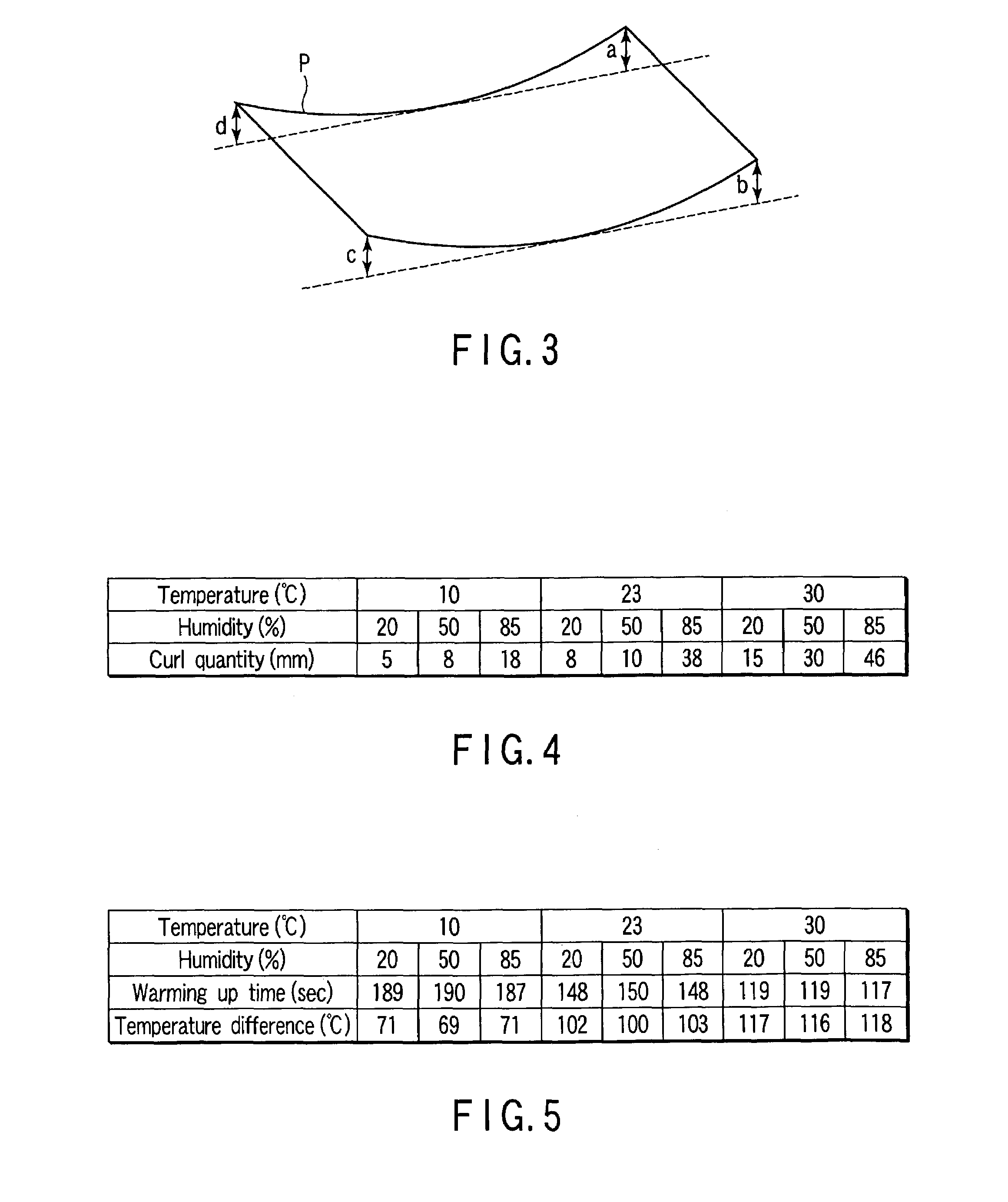
However, as the warming up time is reduced, the risk of producing a large curl on the sheet of paper coming out of the fixing apparatus rises.
As the extent of curl of the sheet of paper increases, so does the likelihood of it being jammed in the conveyance path after the fixing process, thus it may not be properly delivered onto the delivery tray.
Other problems may also arise.

Method used


Image

  • Fixing apparatus
  • Fixing apparatus
  • Fixing apparatus

Examples


Embodiment Construction

[0019]The embodiment of the invention will be described with reference to the accompanying drawings.

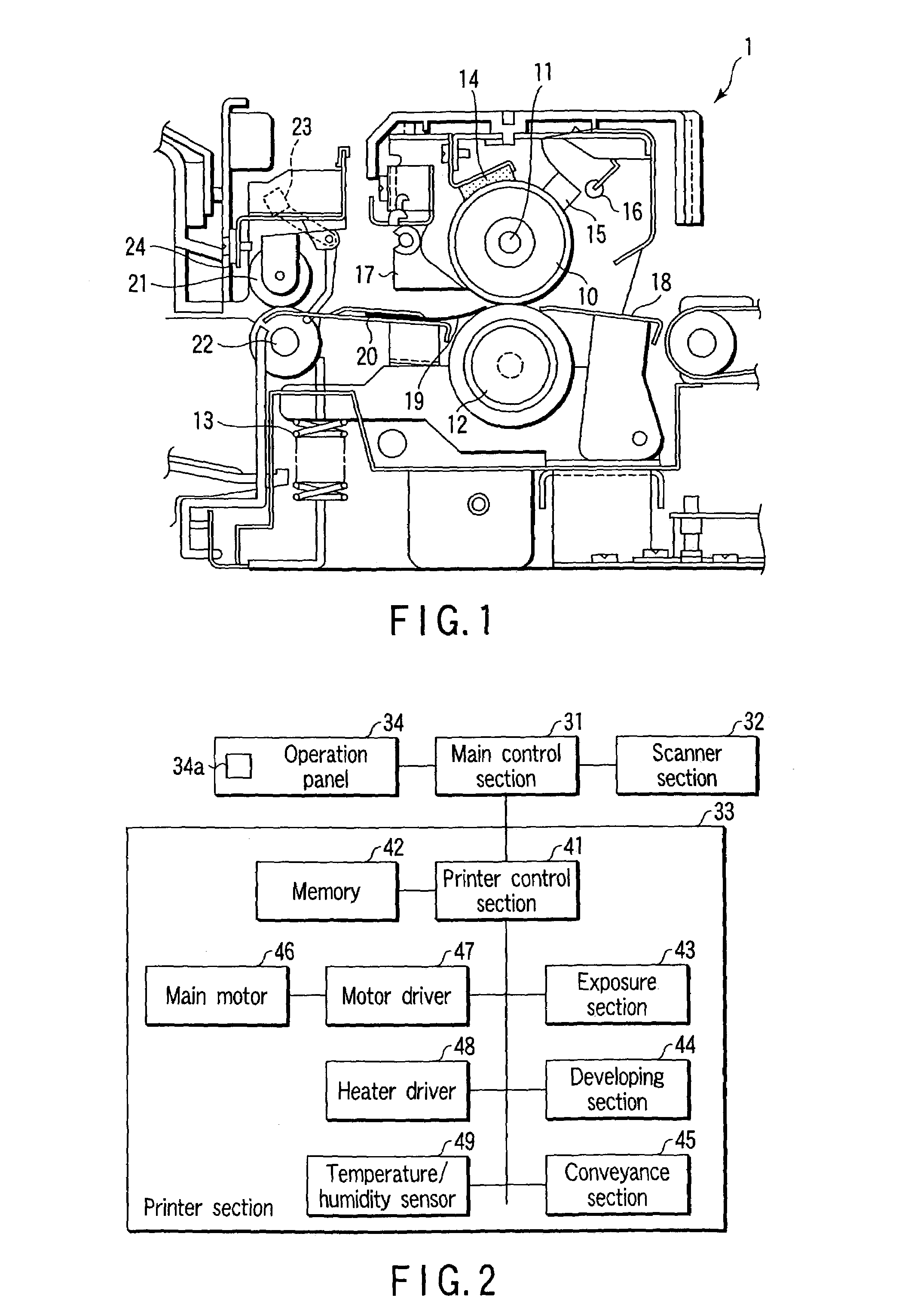
[0020]FIG. 1 is a schematic view showing the configuration of a fixing unit (fixing apparatus) applied to an image forming apparatus described in Jpn. Pat. Appln. KOKAI Publication No. 5-35148. As shown in FIG. 1, the fixing unit 1 comprises a heat roller 10, a heater 11, a press roller 12, a pressure spring 13, a cleaning felt 14, a thermistor 15, a temperature fuse 16, a peeling claw 17, a paper guide 18, a scraper 19, another paper guide 20, a delivery roller 21, another delivery roller 22, a delivery switch 23 and a charge eliminating brush 24.

[0021]The heat roller 10 contains the heater 11. The heater 11 may typically be formed by using a heating lamp or an IH heater. The press roller 12 is pressed against and held in contact with the heat roller 10 by the pressure spring 13. The heat roller 10 is driven to rotate by a main motor 46, which will be described later. The press rolle...


PUM


Abstract

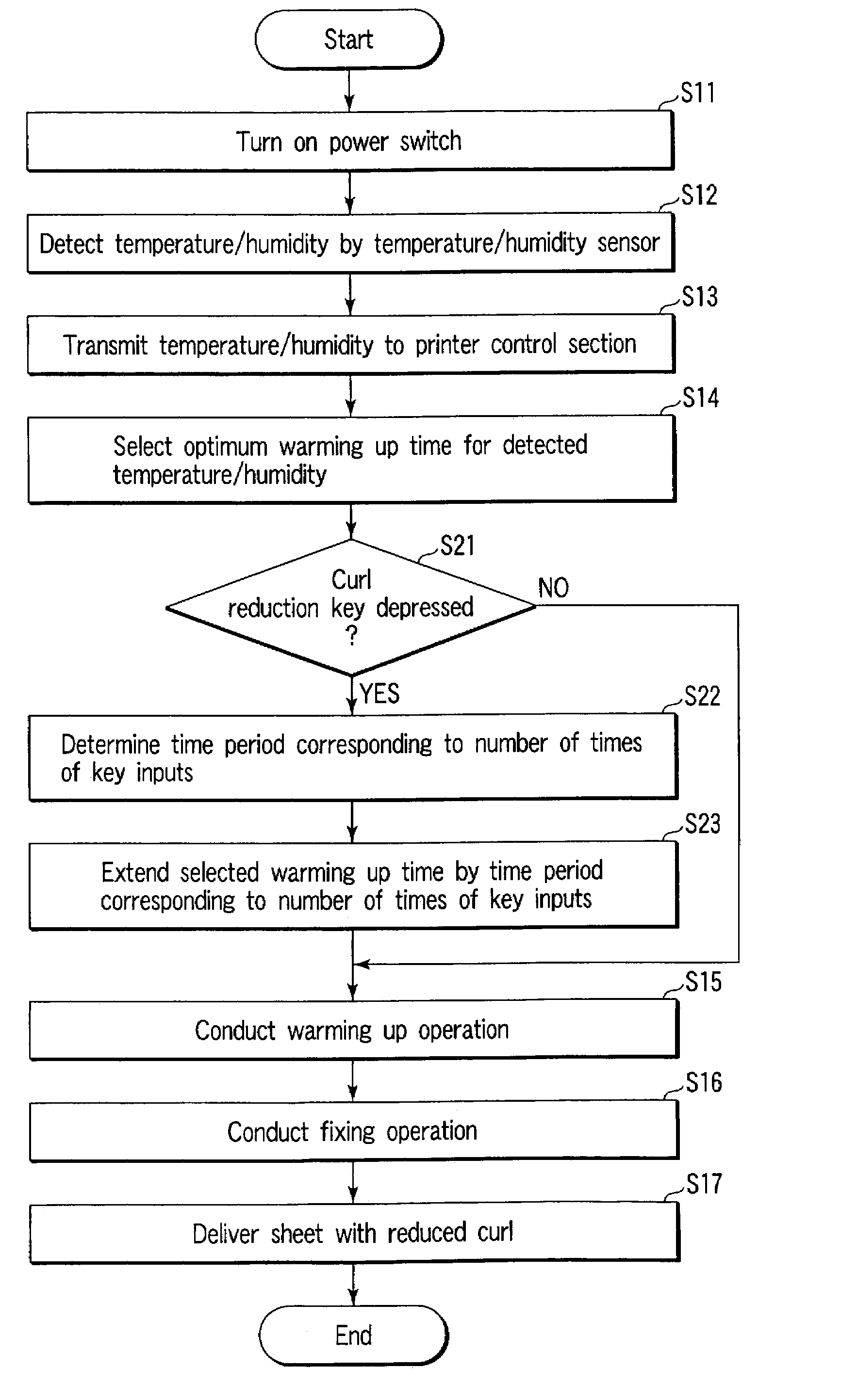
A fixing unit adapted to fix a developing agent onto an image forming medium by way of a heat roller containing a heater and a press roller conducts a warming up operation for the optimum warming up time as determined based on the temperature and the humidity of ambient air detected by a temperature / humidity sensor.

Description

BACKGROUND OF THE INVENTION[0001]This invention relates to a fixing apparatus that can typically be used in an image forming apparatus for the purpose of fixing a developing agent such as toner to the image forming medium.[0002]Conventionally, a fixing apparatus for fixing the toner on an image forming medium is driven for warming up (a pre-run) prior to the fixing operation, in order to secure the ratio of fixing toner on the image forming medium to a required level. For warming up, the heater is turned on and the heat roller is driven to rotate. As a result, the heat roller and the press roller that is held in contact with the heat roller are warmed. The fixing ratio of fixing the developing agent to the image forming medium is secured to a required level by such a warming up operation.[0003]The major objective of such a warming up operation is to secure the fixing ratio to a required level. The warming up time of the warming up operation that is performed for the entire apparatus...

Claims


Application Information

Patent Timeline
Patent Type & Authority Patents(United States)
IPC IPC(8): G03G15/00G03G15/20
CPCG03G15/205
Inventor SHISHIKURA, KENICHIRO
Owner KK TOSHIBA
Learn More