
Bending machine for profiles and relative bending method

Active Publication Date: 2007-08-28
M E P MASCH ELECTRONICS PIEGATRICI SPA
View PDF16 Cites 3 Cited by
  • Summary
  • Abstract
  • Description
  • Claims
  • Application Information

AI Technical Summary

Benefits of technology

[0016]The purpose of the invention is to achieve a bending machine for profiles already sheared to size, and a relative method, which will allow the operator to load said machine with said profiles while standing in a position sufficiently removed from the bending means so that he does not run the risk of accidents during the shearing and bending steps.
[0017]Another purpose is to reduce the risk that the residual torsions present in the straight bars to be bent are released during the feed and bending operations, prejudicing the precision and quality of the bends.
[0024]During the passage between said two positions, the rollers of the driver grip on the profile with a pincer effect; this prevents the profile itself from rotating on its own axis, thus allowing to obtain perfectly parallel bends.
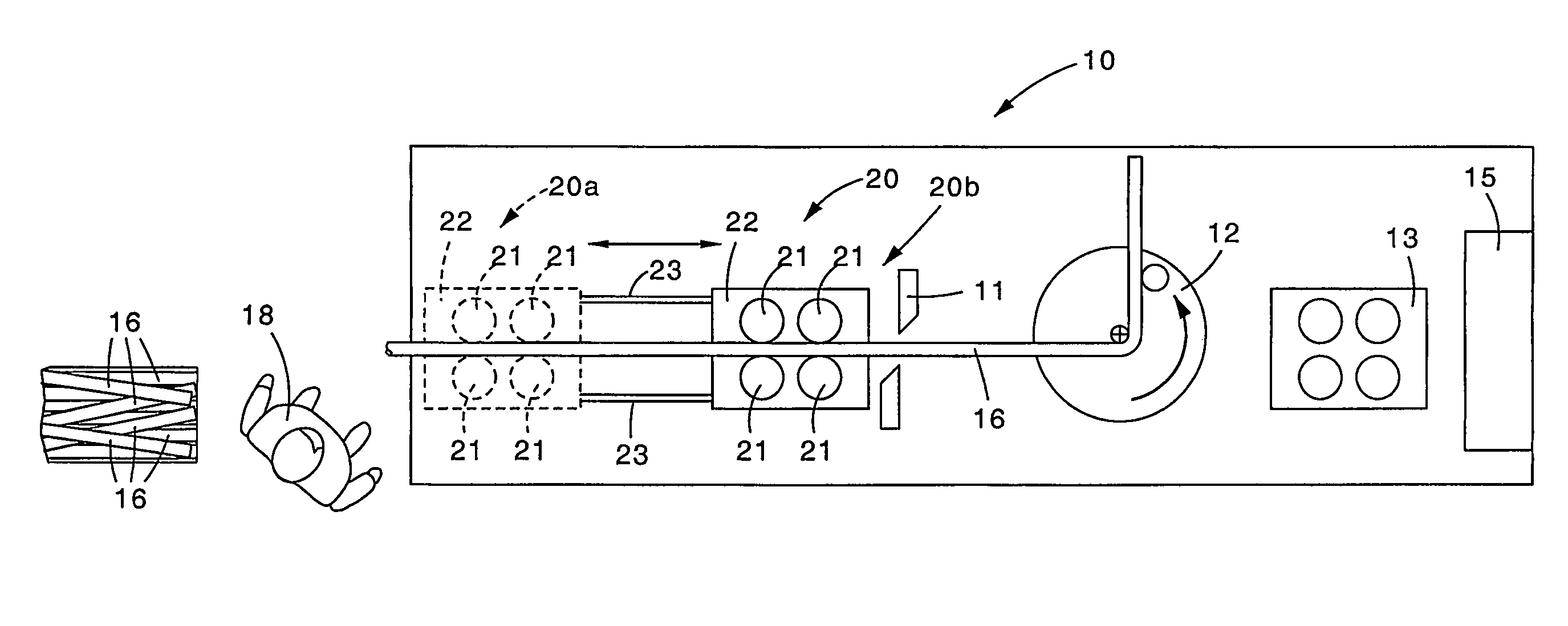
[0029]With the bending machine as described heretofore, the operator can position himself sufficiently remote from the shearing means and bending means, since it is the drawing assembly, or at least a part of it, which moves from a loading zone, where the operator can position himself, to a drawing zone in proximity with the shearing means and bending means.
[0030]With the invention therefore the safety of the operator is facilitated, and in any case, during the drawing / feeding steps, the drawing assembly is kept in a position near the bending unit. Moreover, in the first advance step of the profile the drawing assembly acts thereon with a pincer effect, thus preventing axial rotations and torsions of the profile.

Problems solved by technology

This has a negative effect on the quality, precision and planarity of the bends themselves and on the final products obtained.
At the same time the nearness of the drawing assembly to the bending means makes the operator responsible for loading the machine more exposed to the danger of accidents and injury; in fact, in order to load the profiles into the drawing assembly, for example by removing them from a bundle, the operator has to be very near the shearing means and the bending means, with the risk of being hit by shavings, fragments or the profile itself during the bending step.
Moreover, since the torsions of the bar are released as it advances and is bent, the bent portion can rise up for quite a large amount from the ideal bending plane, with the risk of hitting the operator.

Method used


Image

  • Bending machine for profiles and relative bending method
  • Bending machine for profiles and relative bending method
  • Bending machine for profiles and relative bending method

Examples


Embodiment Construction

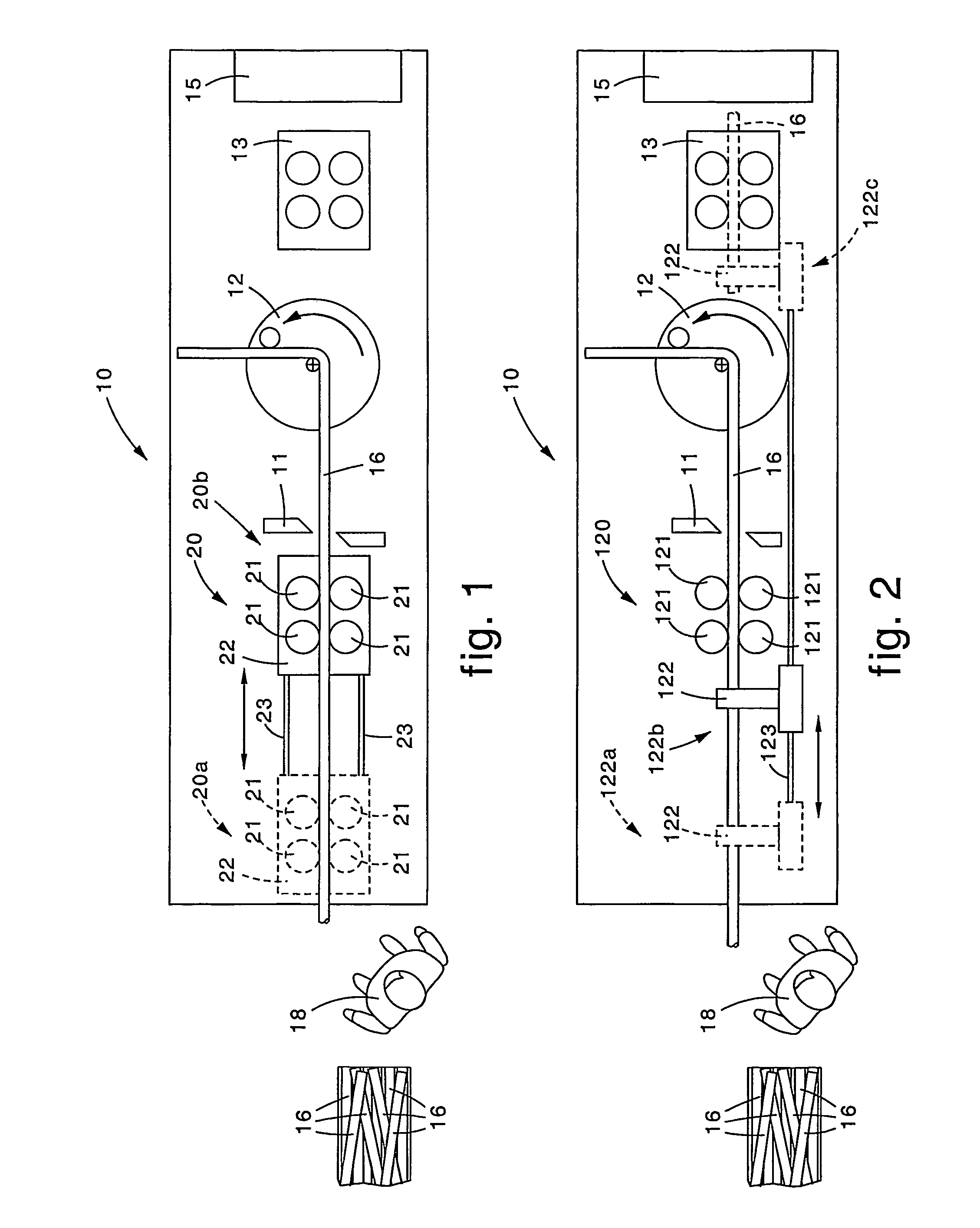
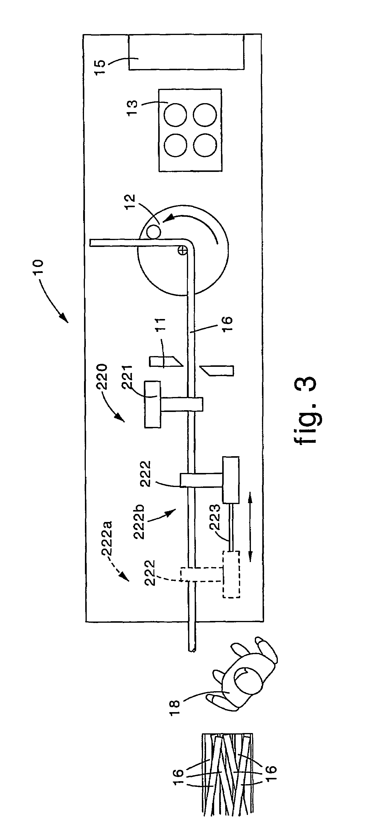
[0036]With reference to FIG. 1, a bending machine 10 for profiles 16 already sheared to size, in particular a straight bar, is shown in a first form of embodiment and comprises in succession a leading end drawing assembly 20, a shears 11, a rotary disk bending unit 12, a trailing end drawing assembly 13, possibly retractable, and a retaining element 15 able to prevent the bent segments of the profile 16 from rising up with respect to an ideal plane as the bending operations proceed.

[0037]In a first embodiment shown in FIG. 1, the leading end drawing assembly 20 comprises a driver with two pairs of rollers 21, assembled on a trolley 22. Said trolley 22 can slide on two guides or tracks 23 and is movable between a first loading position 20a (shown by dashes in FIG. 1), wherein an operator 18 responsible for loading the profiles 16 can position himself, in cooperation with a site wherein said profiles 16 are accumulated, and a second drawing position 20b (shown by a continuous line in ...


PUM

PropertyMeasurementUnit
Pressureaaaaaaaaaa
Timeaaaaaaaaaa
Sizeaaaaaaaaaa

Abstract

Bending machine for profiles in the form of bars sheared to size, including at least a drawing assembly, shearing apparatus and bending apparatus. At least part of the drawing assembly is movable between a first loading position, wherein it is upstream of and remote from the bending apparatus to take at least one of the bars sheared to size from an accumulation site, and a second drawing position, wherein it is upstream of and in proximity with the bending apparatus to draw / feed at least one bar towards the shearing apparatus and the bending apparatus and to cooperate with the shearing apparatus and the bending apparatus in performing the bending cycle.

Description

[0001]This application is a 371 of PCT / IB02 / 02798, filed Jul. 18, 2002.FIELD OF THE INVENTION[0002]The present invention concerns a bending machine for profiles, already sheared to size, such as for example round pieces for reinforcement purposes or suchlike, of the type comprising at least a drawing assembly, shearing means and bending means; the invention also concerns the connected bending method.[0003]At least part of the drawing assembly of the bending machine according to the present invention is movable from a first loading position, wherein it is remote from the bending means, to a second drawing position wherein it is in proximity with said drawing means.[0004]In the first loading position, the movable part of the drawing assembly is able to pick up the already sheared to size profile from an accumulation site, while in the second drawing position the drawing assembly is able to make the profile advance in order to perform the bending cycle.[0005]The invention is applied pa...

Claims


Application Information

Patent Timeline
IPC IPC(8): B21D7/022B21D11/12B21D43/10
CPCB21D11/12B21D43/10
Inventor DEL FABRO, GIORGIODEL FABRO, MARCELLO
Owner M E P MASCH ELECTRONICS PIEGATRICI SPA
Learn More