Postoperative drainage device for breast cancer

A breast cancer and driving device technology, applied in the direction of suction equipment, etc., can solve problems such as inability to adjust negative pressure, achieve precise control accuracy, and ensure comfort

Inactive Publication Date: 2022-04-26
成都市龙泉驿区第一人民医院
View PDF7 Cites 2 Cited by
  • Summary
  • Abstract
  • Description
  • Claims
  • Application Information

AI Technical Summary

Problems solved by technology

[0004] The invention discloses a postoperative drainage device for breast cancer, which aims to solve the problem that the existing negative pressure drainage device mentioned in the background technology cannot adjust the negative pressure according to different situations

Method used


Image

  • Postoperative drainage device for breast cancer
  • Postoperative drainage device for breast cancer
  • Postoperative drainage device for breast cancer

Examples


Embodiment 1

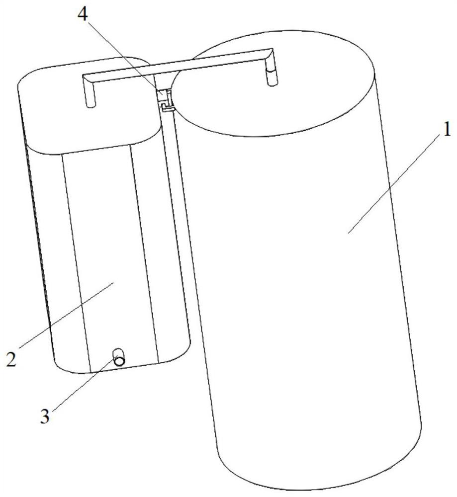
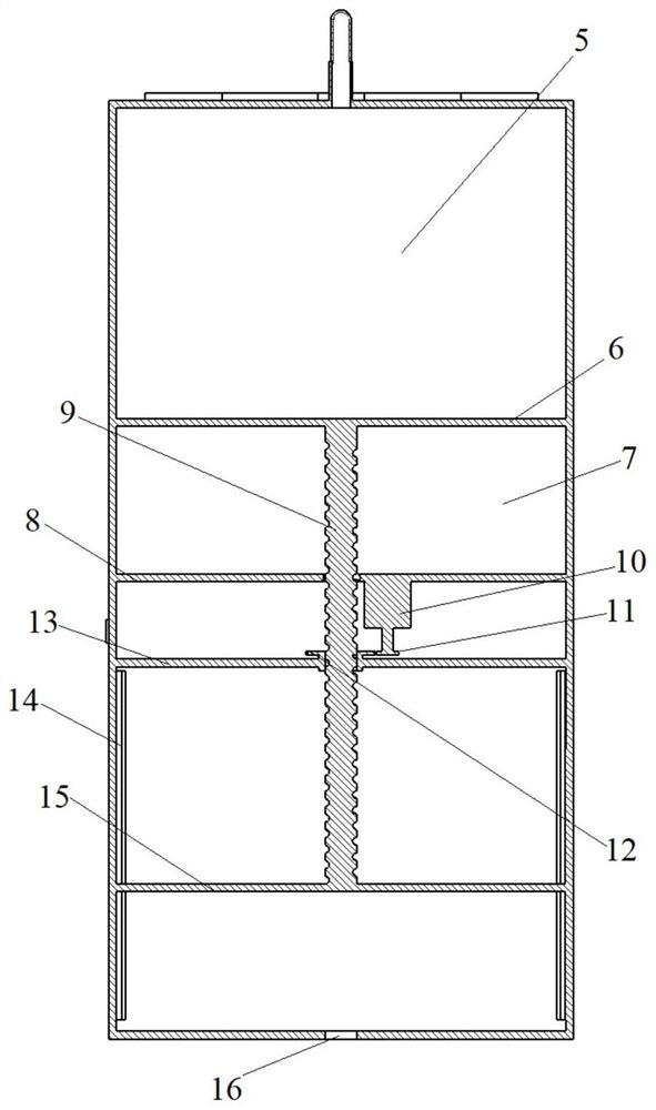
[0031] Embodiment 1: see attached figure 1 And attached figure 2As shown, a postoperative drainage device for breast cancer includes a negative pressure chamber 1 and a partition 8 arranged in the negative pressure chamber 1; the partition 8 divides the negative pressure chamber 1 into an equipment chamber and a negative pressure chamber ; The negative pressure chamber is provided with a piston 6, the contact surface of the piston 6 and the inner side wall of the negative pressure chamber is covered with a sealing ring, and the negative pressure chamber is divided into a front chamber 5 and a rear chamber by the piston 6 7. The front chamber 5 is connected to the fluid chamber 2 through a pipeline, and the fluid chamber 2 is connected to the drainage tube 3; the piston 6 is connected to the piston rod 9, and the piston rod 9 passes through the rear chamber 7 It penetrates through the partition plate 8 and extends into the equipment chamber, and the equipment chamber is provi...

Embodiment 2

[0044] Embodiment 2: The difference with the above-mentioned embodiment 1 is that the driving device of the present embodiment 2 adopts an electric push rod, and the telescopic end of the electric push rod is connected with the piston rod 9; the electric push rod drives the piston rod 9 to move back and forth, Then drive the piston 6 to move back and forth. However, in terms of Embodiment 1 and Embodiment 2, Embodiment 1 is preferred in the present invention because the control precision of Embodiment 1 is higher than that of Embodiment 2.

[0045] In the present invention, the touch display screen with control function is connected with the motor 10, and the detection information of the pressure sensor and the liquid level sensor is obtained through the display screen to control the speed of the motor 10 or to control the start and stop of the motor 10; The screen reports to the police, and reminds relevant personnel to close motor 10. However, touch display screens with con...


PUM


Abstract

The invention belongs to the technical field of medical drainage devices, and particularly relates to a breast cancer postoperative drainage device which comprises a negative pressure bin and a partition plate arranged in the negative pressure bin. The negative pressure bin is divided into an equipment chamber and a negative pressure chamber by the partition plate; a piston is arranged in the negative pressure chamber, and the negative pressure chamber is divided into a front chamber and a rear chamber through the piston; the front chamber is communicated with a liquid accumulation chamber through a pipeline, and the liquid accumulation chamber is communicated with a drainage tube; a piston rod is connected to the piston, the piston rod penetrates through the partition plate through the rear cavity and extends into the equipment cavity, and a driving device capable of driving the piston rod to move and further driving the piston to move back and forth in the negative pressure cavity is arranged in the equipment cavity. The driving device is arranged to drive the piston to move towards one end close to the equipment cavity, so that negative pressure formed by the hydrops cavity acts on an operation wound surface connected with the drainage tube, and negative pressure drainage force is achieved; and the adjustment of the negative pressure can be realized by adjusting the output power of the driving device.

Description

technical field [0001] The invention belongs to the technical field of medical drainage devices, and in particular relates to a drainage device after breast cancer surgery. Background technique [0002] At present, the surgical methods for breast cancer in my country mainly include the following types, namely, classic radical mastectomy, modified radical mastectomy, extended radical mastectomy, simple mastectomy and partial mastectomy, etc. Generally, except for partial mastectomy, the rest of breast cancer Drainage is required after surgery. The reason is that the surgical wound is large, and at the same time, the lymph nodes in the armpit must be cleaned. Under the skin, therefore, it is necessary to prevent the drainage tube and use continuous negative pressure suction to continuously suck out the accumulated blood and exudate, so that the skin flap can stick to the wound surface, which is conducive to wound healing and prevents necrosis and infection of the skin flap. [...

Claims


Application Information

Patent Timeline
Patent Type & Authority Applications(China)
IPC IPC(8): A61M1/00
CPCA61M2205/3331A61M2205/3379A61M2205/18A61M2205/583A61M2210/1007A61M2210/005
Inventor 蒋延凤邓茜茜黄吉燕蒋美玲魏玲
Owner 成都市龙泉驿区第一人民医院
Why Eureka
Try Eureka