Corner shearing device system

A technology of power device and upper shear seat, which is applied in the direction of shear device, shear machine equipment, metal processing equipment, etc., can solve the problems of low processing efficiency, time-consuming and laborious, inconvenient replacement, etc., and achieve high processing efficiency, convenient use, Labor saving effect

Inactive Publication Date: 2014-03-26
天津市天港机械有限公司
View PDF0 Cites 1 Cited by
  • Summary
  • Abstract
  • Description
  • Claims
  • Application Information

AI Technical Summary

Problems solved by technology

Existing angle shearing machines are generally operated manually, and the plate to be processed needs to be picked and placed by hand. Only one cut can be cut at a time, and the processing efficiency is low.
Moreover, only one-sided processing can be carried out, which is time-consuming and labor-intensive
The blades used for shearing are generally fixed with bolts, which is inconvenient to replace

Method used


Image

  • Corner shearing device system

Examples


Embodiment Construction

[0019] The present invention will be described in detail below in conjunction with the accompanying drawings.

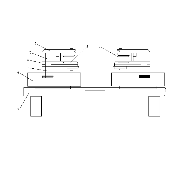
[0020] Such as figure 1 As shown, the present invention is a kind of angle cutting device system, comprises upper blade 1, lower blade 2, upper shear seat 3, lower shear seat 4, guide post 5, fixed seat 6, support 7 and power unit, support 7 There are slide rails on the top, and the bottom of the fixed seat 6 is provided with a draw-in slot for use with the slide rail. The fixed seat 6 is installed on the slide rail of the support 7. There are two fixed seats 6, which are respectively located on both sides of the support 7. The slide rail The middle part is provided with a strip-shaped through hole, and the bottom of the fixed seat 6 is provided with a screw hole above the strip-shaped through hole. The fixed seat 6 is fixed on the slide rail by bolts; the guide post 5 is fixed on the fixed seat 6, and the upper blade 1 is installed on The upper shear seat 3 and the...


PUM


Abstract

The invention provides a corner shearing device system. The corner shearing device system comprises upper blades, lower blades, upper shear bases, lower shear bases, guide posts, fixed bases, a support and a power device, wherein a sliding rail is arranged on the support, clamping grooves matched with the sliding rail for use are formed in the bottoms of the fixed bases, the fixed bases are arranged on the sliding rail of the support, the fixed bases are two in number and located on two sides of the support, a strip-shaped through hole is formed in the middle of the sliding rail, screw holes located above the strip-shaped through hole are formed in the bottoms of the fixed base, and the fixed bases are fixed on the sliding rail through bolts; the guide posts are fixed on the fixed bases, the upper blades are arranged on the upper shear bases, the lower blades are arranged on the lower shear bases, and the upper shear bases are driven by the power device and can do vertical reciprocating movement relative to the lower shear bases along the guide posts. The corner shearing device system has the advantages of being convenient to use and high in machining efficiency.

Description

[0001] technical field [0002] The invention belongs to the field of mechanical processing equipment, in particular to an angle shearing device system. Background technique [0003] The corner shearing machine is a machine that punches out corners on the edge of the sheet, which can be used in the production process of the pipe division. After the sheet with the corners punched out is folded, the end can be made into the flange of the air duct. [0004] The working principle of the angle shearing machine is similar to that of a punching machine. It includes a set of upper blades that can move up and down and a set of fixed lower blades. When the upper blade moves down and cooperates with the lower blade, it can Punch out the notch. Existing angle shearing machines are generally manually operated, and the plate to be processed needs to be picked and placed by hand, and only one slit can be cut at a time, and the processing efficiency is low. Moreover, only one-sided proces...

Claims


Application Information

Patent Timeline
Patent Type & Authority Applications(China)
IPC IPC(8): B23D15/00
Inventor 王绍航
Owner 天津市天港机械有限公司
Why Eureka
Try Eureka