Gear grinding and deburring device

A technology for deburring and gear removal, which is used in grinding drives, grinding/polishing safety devices, grinding machines, etc., and can solve problems such as uneven grinding of gear tooth grooves.

Inactive Publication Date: 2018-08-03
滁州伏特威电气技术有限公司
View PDF7 Cites 1 Cited by
  • Summary
  • Abstract
  • Description
  • Claims
  • Application Information

AI Technical Summary

Problems solved by technology

[0004] The present invention provides a gear grinding and deburring device in order to solve the problem that the tooth groove of the gear cannot be evenly ground

Method used


Image

  • Gear grinding and deburring device
  • Gear grinding and deburring device

Examples


Embodiment Construction

[0015] The present invention will be described in further detail below by means of specific embodiments:

[0016] The reference signs in the drawings of the description include:

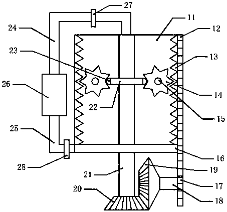
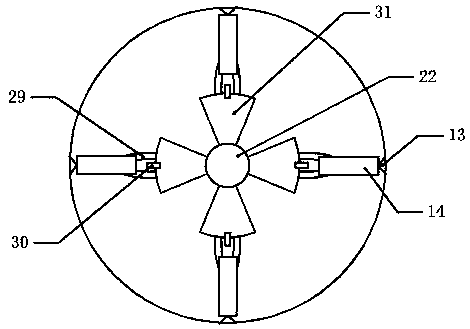
[0017] Mandrel 11, first rack 12, second rack 13, gear 14, transverse shaft 15, collecting tank 16, spur gear 17, first rotating shaft 18, first bevel gear 19, second bevel gear 20, second Rotating shaft 21, grinding wheel 22, air bag 23, air intake pipe 24, exhaust pipe 25, blower 26, one-way air intake valve 27, one-way air extraction valve 28, fine sandpaper 29, one-way air intake hole 30, frosted fan blade 31 .

[0018] Such as figure 1 The shown gear grinding and deburring device includes a mandrel 11, a hollow second rotating shaft 21 is installed in the central position of the mandrel 11, and 50 air outlet holes are provided on the second rotating shaft 21, and a hollow frosting is fixedly installed on the middle of the second rotating shaft 21. wheel 22, such as figure 2 The shown grindi...


PUM


Abstract

The invention relates to a gear processing device, and particularly to a gear polishing and deburring device which is characterized in that air outlets are formed in a second rotating shaft in a working barrel; grinding blades are arranged on a hollow grinding wheel fixedly mounted on the second rotating shaft; an air bag is mounted on each of the grinding blades; the outer side of each of the air bags is wrapped with fine sandpaper; a one-way air inlet is formed in the connection part of each of the air bags and the corresponding grinding blade; a plurality of transverse shafts are arranged on the outer side of the grinding wheel; a gear is arranged on each of the transverse shafts; second toothed racks are arranged on the inner wall of the working barrel and meshed with teeth on the gears; a first toothed rack is fixedly mounted on the outer side of the working barrel; a second bevel gear is mounted at the lower end of the second rotating shaft; a first bevel gear is arranged on the outer side of the second bevel gear and meshed with the second bevel gear; a first rotating shaft is fixed at the middle of the first bevel gear; a straight gear is arranged at the right end of the first rotating shaft and meshed with a first toothed rack; an air blower is arranged outside the working barrel and movably connected with the second rotating shaft. According to the gear polishing and deburring device, the problem that tooth grooves of the gears cannot be polished uniformly is solved.

Description

technical field [0001] The invention relates to a gear processing device, in particular to a gear grinding and deburring device. Background technique [0002] A gear is a mechanical element with teeth on the rim that can continuously mesh to transmit motion and power. The application of gears in transmission has appeared very early. It appears that with the development of production, the stability of gear operation has been paid attention to, and the gear needs to be polished after production. Grinding the saw teeth on the gear is difficult to operate. Generally, the grinding wheel is fixed. Manually adjust the height of the saw gear and then adjust the rotation of the saw gear, so as to grind each saw tooth on the saw gear. The adjustment operation is troublesome and the work low efficiency. [0003] The invention patent of authorized notification number CN 103331489B discloses a sawtooth grinding device on the saw gear, which includes a frame on which the saw gear is ins...

Claims


Application Information

Patent Timeline
Patent Type & Authority Patents(China)
IPC IPC(8): B24B9/04B24B41/02B24B41/06B24B47/20B24B55/06
CPCB24B9/04B24B41/02B24B41/06B24B47/20B24B55/06
Inventor 曾义杰
Owner 滁州伏特威电气技术有限公司
Why Eureka
Try Eureka