

Polishing pad, method of producing same, and polishing method
Inactive Publication Date: 2005-01-27
NIHON MICRO COATING
View PDF16 Cites 20 Cited by
- Summary
- Abstract
- Description
- Claims
- Application Information
AI Technical Summary
Benefits of technology
Grooves are formed on the surface of the polishing pad of this invention for collecting polluting or contaminating objects such as debris generated during the polishing operation such that such objects can be discharged ou
Problems solved by technology
If a conventional flexible and elastic polishing pad is used to polish the surface of such a top layer, a gentle unevenne
Method used
View moreImage
Smart ImageViewing Examples

Examples
 PUM
| Property | Measurement | Unit |
|---|---|---|
| Thickness | aaaaa | aaaaa |
| Pressure | aaaaa | aaaaa |
| Diameter | aaaaa | aaaaa |
Abstract
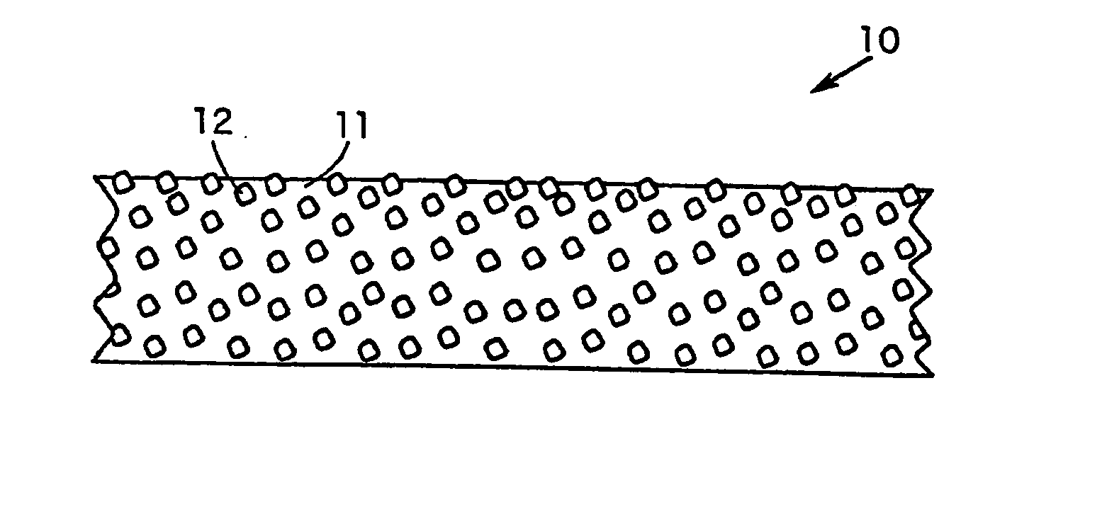
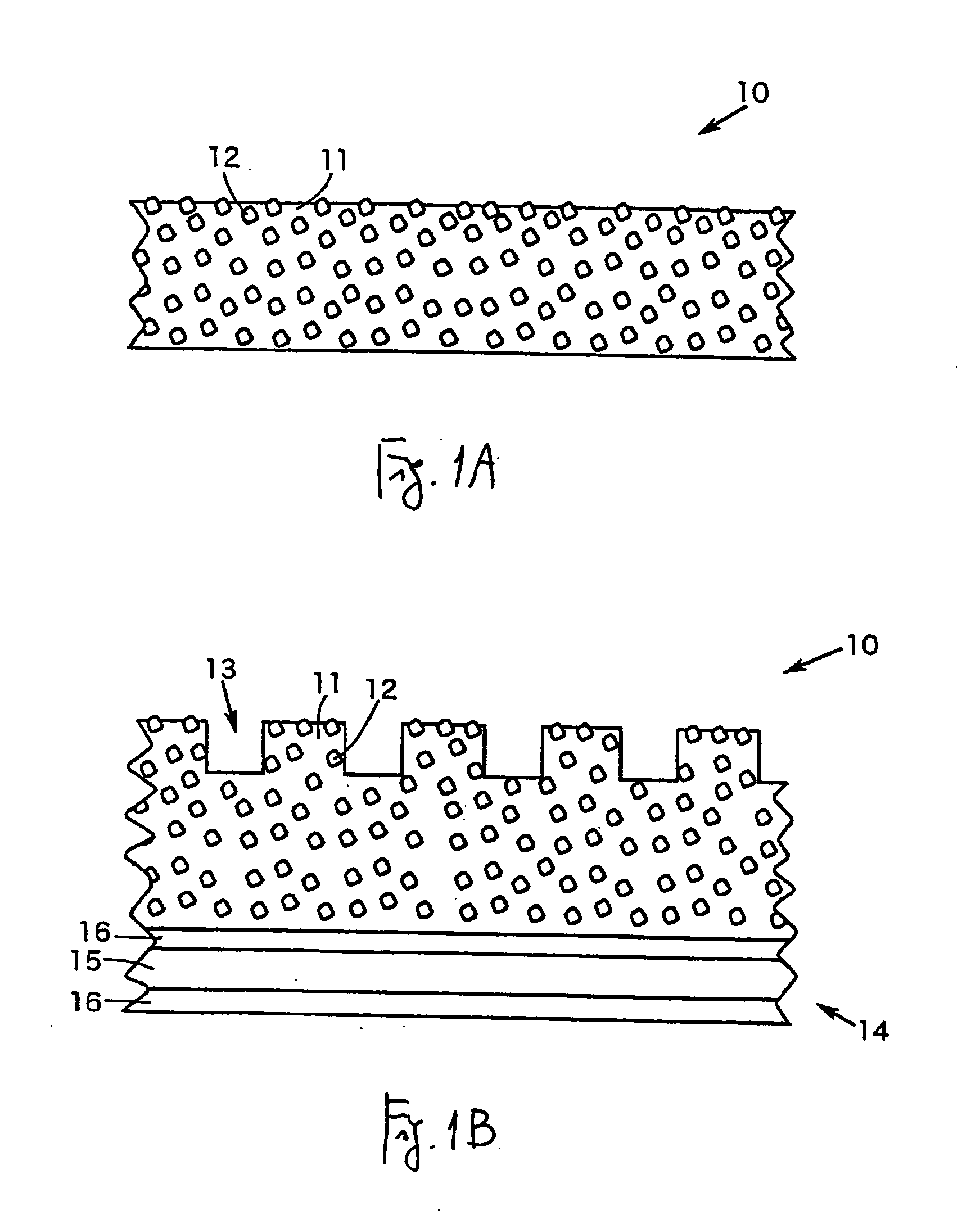
A polishing pad is formed with a non-foamed member shaped as a plate having a flat surface and abrading particles affixed inside and on the surfaces of this non-foamed member. Its average surface roughness is in the range of 0.5 μm-10 μm, and its Shore D hardness is within the range of 50-85. Grooves are formed on the surface of the polishing pad for collecting debris generated during the polishing operation and serving also as flow routes of a polishing liquid for distributing it uniformly over the surface of the polishing pad.
Description
Priority is claimed on Japanese Patent Application 2003-174258 filed Jun. 19, 2003. BACKGROUND OF THE INVENTION This invention relates to a polishing pad to be used for polishing the surface of a workpiece made of a metallic material, ceramics or glass, as well as a method of producing such a polishing pad. In particular, the invention relates to such a polishing pad used for polishing the surface of a workpiece such as a semiconductor wafer, a semiconductor device wafer, a liquid crystal display element, a thin-film imaging device, a magnetic disk substrate and an optical disk substrate, a method of producing such a polishing pad and a method of polishing. Semiconductor devices and magnetic disks are used as principal electronic components of electronic apparatus such as telephones, cameras and computers in order to control their functions and to store or display data. A workpiece such as a semiconductor wafer used in such an electronic component is made into a product after hav...
Claims
Login to View More Application Information
Patent Timeline
 IPC IPC(8): B24D3/00B24D7/02B24D3/28B24D3/30B24D7/00H01L21/304
CPCB24D3/30B24B37/26
InventorSAITO, MITSURUTAMURA, JUNIZUMI, TOSHIHIROKOBAYASHI, TOSHIHIRONAGAMINE, TAKUYAMILLER, CLAUGHTON
OwnerNIHON MICRO COATING