Automatic maintenance device for steel wire rope of sluice winch type hoist

A wire rope and winch-type technology, which is applied in the field of automatic maintenance devices for wire ropes, can solve problems such as damage, corrosion and damage of some sections of the wire rope, easy adhesion of dust to the wire rope, etc., and achieve the effect of improving stability and oiling efficiency

Inactive Publication Date: 2021-11-12
陈俊杰
View PDF0 Cites 2 Cited by
  • Summary
  • Abstract
  • Description
  • Claims
  • Application Information

AI Technical Summary

Problems solved by technology

[0002] The steel wire rope on the hoist hoist of the sluice gate needs regular maintenance every year. Due to the influence of dust near the sluice gate, the surface of the steel wire rope is easy to adhere to dust. With the extension of the adhesion time, the steel wire rope is easy to be corroded and damaged. Set up a device for maintaining the wire rope
[0003] However, the existing maintenance device only pays attention to the cleaning and oiling maintenance operations of the steel wire rope, and ignores the control of the winding speed of the steel wire rope. A better maintenance effect cannot be obtained. For example, because the moving speed of the wire rope is too fast, the operation speed of cleaning and oiling cannot keep up. As a result, some sections of the wire rope are only cleaned without oiling, and some sections are only Oiled but not cleaned, it is easy to cause some sections of the wire rope to still have rust damage

Method used


Image

  • Automatic maintenance device for steel wire rope of sluice winch type hoist
  • Automatic maintenance device for steel wire rope of sluice winch type hoist
  • Automatic maintenance device for steel wire rope of sluice winch type hoist

Examples


Embodiment Construction

[0041] In order to make the object, technical solution and advantages of the present invention clearer, the present invention will be further described in detail below in conjunction with the accompanying drawings and embodiments. It should be understood that the specific embodiments described here are only used to explain the present invention, not to limit the present invention.

[0042] Based on the embodiments of the present invention, all other embodiments obtained by persons of ordinary skill in the art without making creative efforts belong to the protection scope of the present invention.

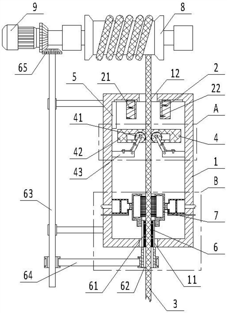
[0043] see figure 1 , is a structural schematic diagram of an automatic wire rope maintenance device for a sluice hoist hoist provided by an embodiment of the present invention. The steel wire rope automatic maintenance device of the sluice hoist hoist includes: a housing 1, a clamping mechanism 2, a maintenance mechanism, a speed measuring mechanism 4, and a controller 5.

[0044...


PUM


Abstract

The invention provides an automatic maintenance device for a steel wire rope of a sluice winch type hoist. The automatic maintenance device comprises a shell, a clamping mechanism, a maintenance mechanism, a speed measuring mechanism and a controller. A rope inlet hole and a rope outlet hole are formed in the shell; the clamping mechanism is arranged on one side of the rope outlet hole; the clamping mechanism comprises a first electromagnet block and a second electromagnet block; the first electromagnet block and the second electromagnet block are arranged on the inner wall of the shell in a sliding manner; the speed measuring mechanism comprises two rolling wheels and a speed measuring sensor, the two rolling wheels abut against the steel wire rope, and rotating shafts of the two rolling wheels are inserted into the speed measuring sensor; the speed measuring sensor can detect the rotating speed of the two rolling wheels and send the rotating speed to the controller, and the controller receives the rotating speed, calculates the average rotating speed and compares the average rotating speed with a set rotating speed value; when the calculated average rotating speed is larger than the set rotating speed value, the controller controls the first electromagnet block and the second electromagnet block to be close to each other; otherwise, stopping moving. The automatic maintenance device for the steel wire rope of the sluice winch type hoist can prevent the movement speed of the steel wire rope from being too high to influence the maintenance effect.

Description

technical field [0001] The invention relates to the technical field of steel wire rope maintenance equipment, in particular to a steel wire rope automatic maintenance device for a sluice hoist hoist. Background technique [0002] The steel wire rope on the hoist hoist of the sluice gate needs regular maintenance every year. Due to the influence of dust near the sluice gate, the surface of the steel wire rope is easy to adhere to dust. With the extension of the adhesion time, the steel wire rope is easy to be corroded and damaged. A device for maintaining the wire rope is provided. [0003] However, the existing maintenance device only pays attention to the cleaning and oiling maintenance operations of the steel wire rope, and ignores the control of the winding speed of the steel wire rope. A better maintenance effect cannot be obtained. For example, because the moving speed of the wire rope is too fast, the operation speed of cleaning and oiling cannot keep up. As a result,...

Claims


Application Information

Patent Timeline
Patent Type & Authority Applications(China)
IPC IPC(8): E02B7/36F16N7/30
CPCE02B7/36F16N7/30
Inventor 陈俊杰李晓华白雪芳
Owner 陈俊杰
Why Eureka
Try Eureka