

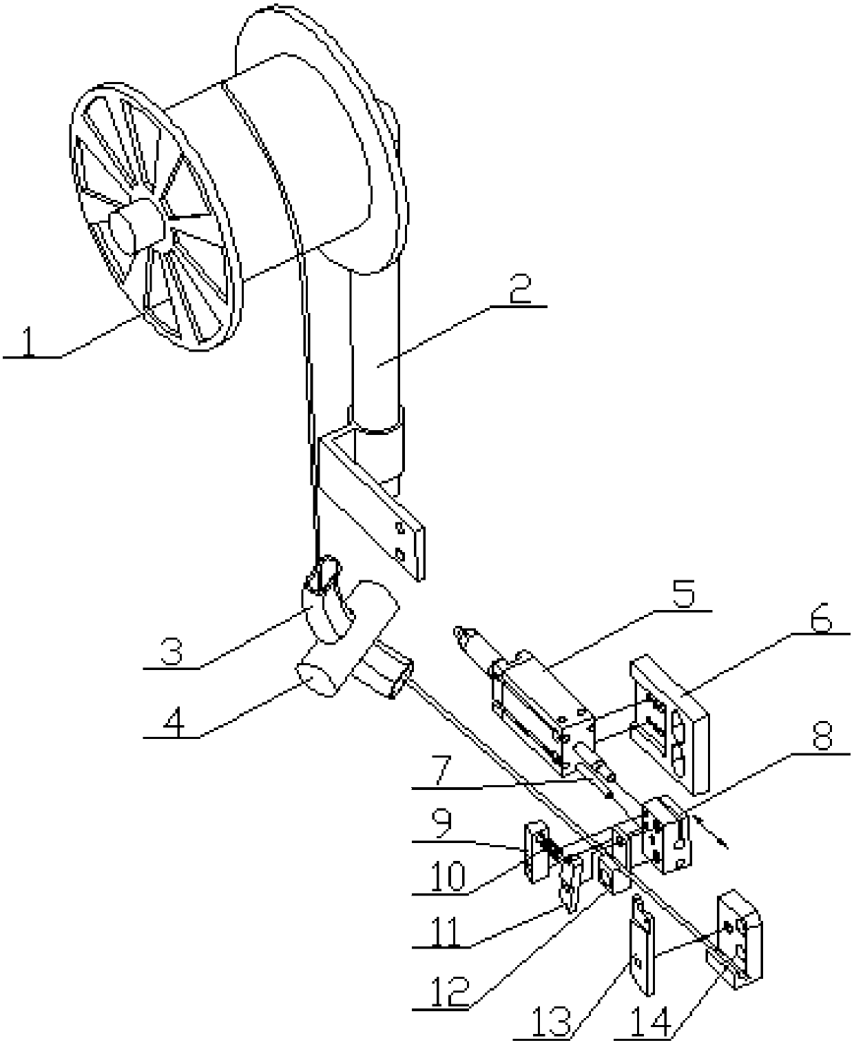
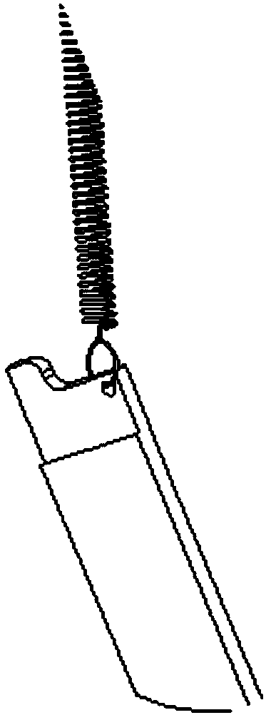
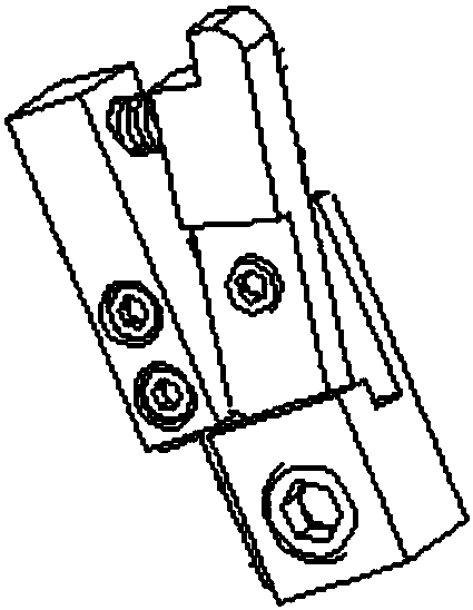
Pneumatic feeding system of copper belt machine
A technology of feeding system and copper belt, which is applied in the direction of conveying filamentous materials, thin material handling, transportation and packaging, etc., can solve the problem of long distance between the feeding wheel and the working mold, cumbersome and inaccurate adjustment of feeding, and affecting the work of the copper belt machine. Accuracy and other issues, to achieve the effect of good feeding rigidity, preventing back-off, and ensuring feeding
- Summary
- Abstract
- Description
- Claims
- Application Information
AI Technical Summary
Problems solved by technology
Method used
Image

Examples
Embodiment Construction
[0022] It should be noted that, in the case of no conflict, the embodiments of the present invention and the features in the embodiments can be combined with each other.
[0023] In describing the present invention, it should be understood that the terms "center", "longitudinal", "transverse", "upper", "lower", "front", "rear", "left", "right", " The orientations or positional relationships indicated by "vertical", "horizontal", "top", "bottom", "inner" and "outer" are based on the orientations or positional relationships shown in the drawings, and are only for the convenience of describing the present invention and Simplified descriptions, rather than indicating or implying that the device or element referred to must have a particular orientation, be constructed and operate in a particular orientation, and thus should not be construed as limiting the invention. In addition, the terms "first", "second", etc. are used for descriptive purposes only, and should not be understood ...
PUM
 Abstract
Description
Claims
Application Information