
Bit holder device

a bit and holder technology, applied in the direction of wrenches, screwdrivers, manufacturing tools, etc., can solve the problems of cumbersome attachment and detachment of the bit and the cylindrical body, and the cylindrical body cannot be removed from the holder body, so as to achieve the effect of easily changing the bit body

Active Publication Date: 2007-08-28
VESSEL IND
View PDF28 Cites 69 Cited by
  • Summary
  • Abstract
  • Description
  • Claims
  • Application Information

AI Technical Summary

Benefits of technology

"The invention is a bit holder device that allows for tightening screws while holding the bit body in place. The device includes a cylindrical cover member that is removably fitted about the bit body and has a magnetic attracting portion for holding the screw. The cover member can be easily removed to change the bit body, and the device facilitates the attachment and removal of a cylindrical body. The technical effects of the invention include easy changing of the bit body without removing it from the chuck of an electric tool and a simplified job of tightening screws."

Problems solved by technology

The use of the cylindrical body has, however, makes the attachment and detachment of the bit and cylindrical bodies cumbersome, since two jobs, that is, the job of removing the bit body from the chuck of the electric tool and the job of removing the cylindrical body from the bit body are required for changing the bit body and attaching the cylindrical body to another bit body.
The device described in the German Patent Publication has, however, a drawback that the cylindrical body cannot be removed from the holder body.Patent Literature 1: JP-A-2000-246658Patent Literature 2: German Patent Publication DE10148943A1

Method used


Image

  • Bit holder device
  • Bit holder device
  • Bit holder device

Examples


first embodiment

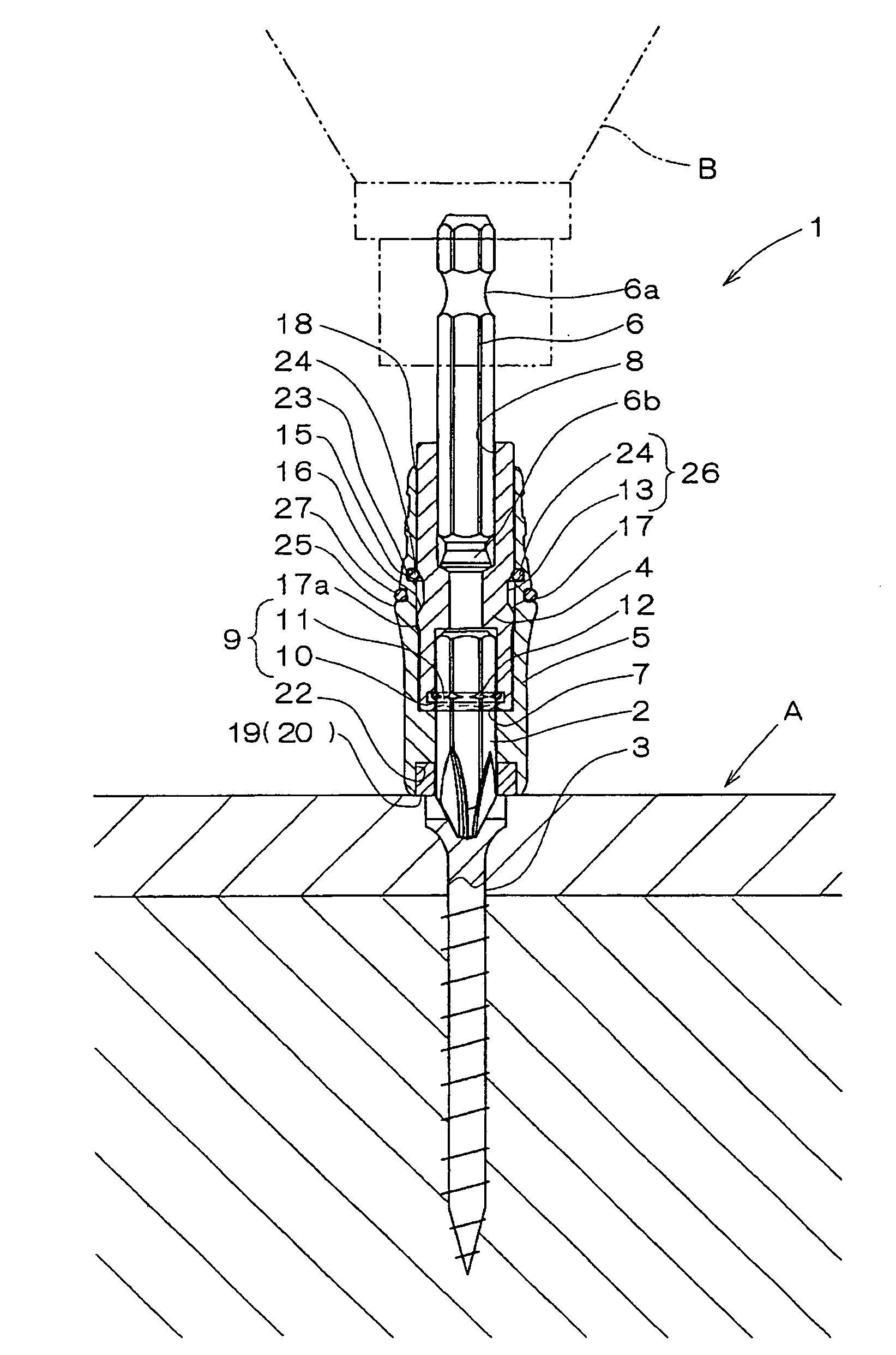
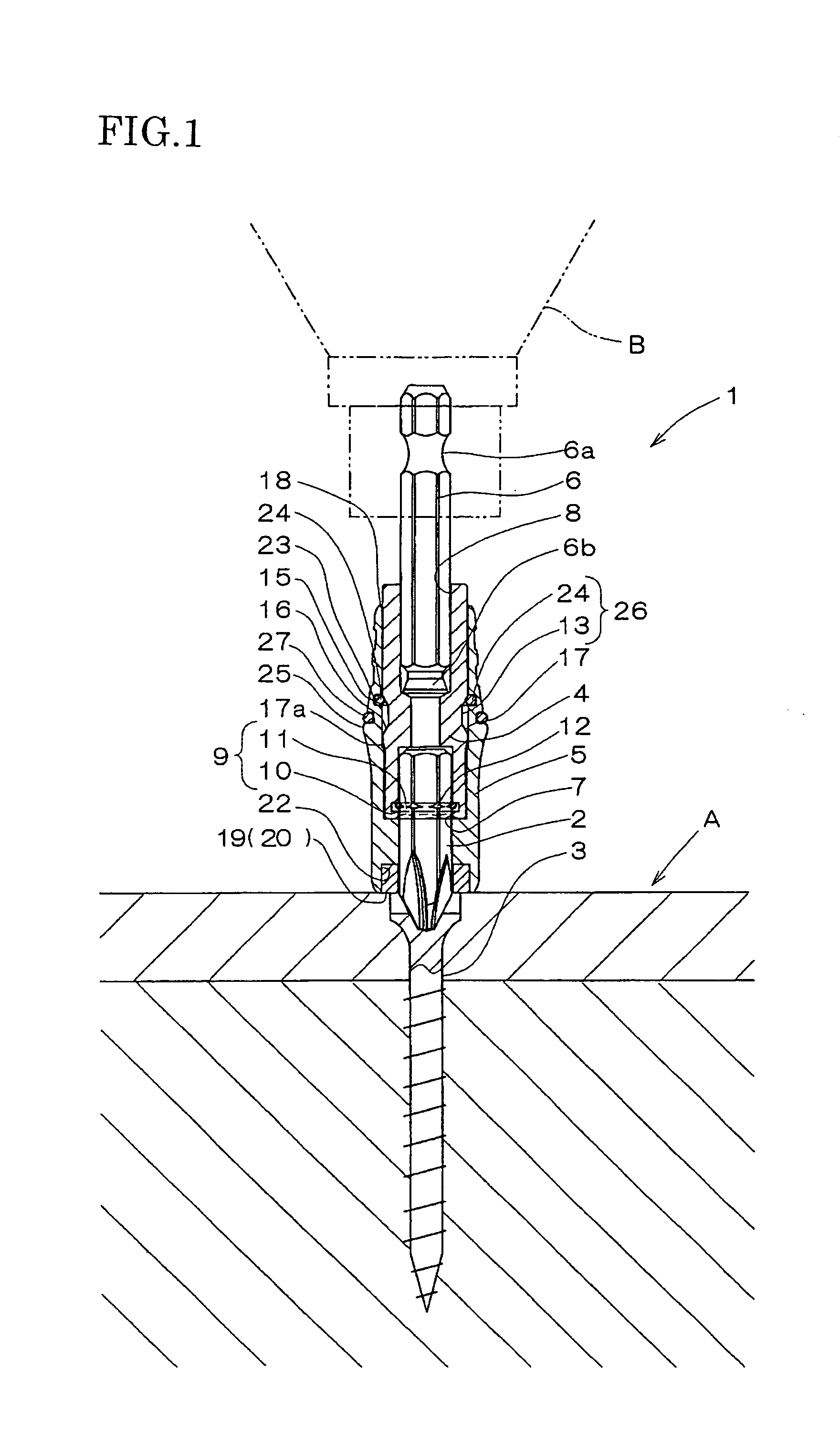
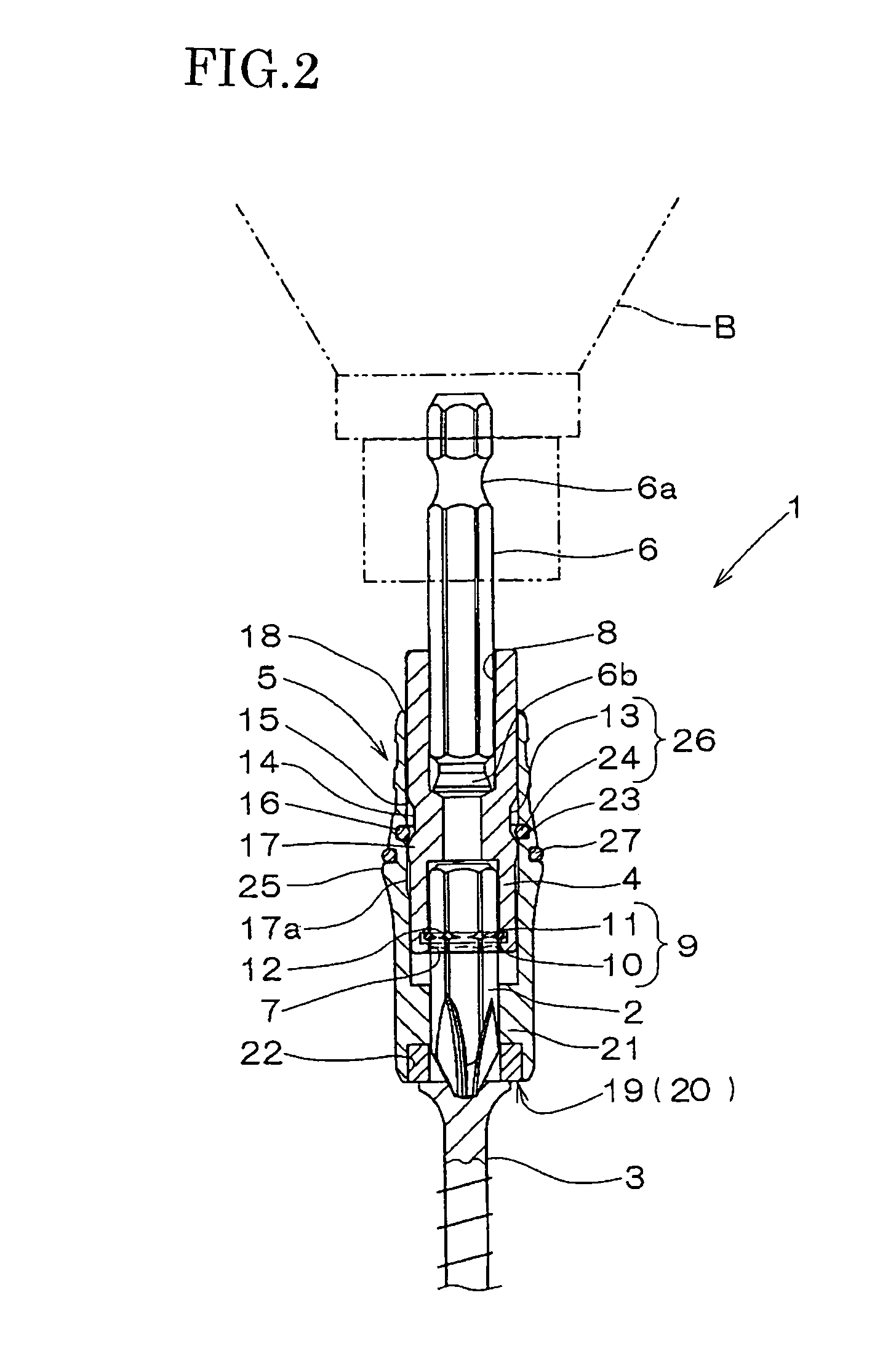
[0055]FIGS. 1 to 6 show this invention.

[0056]The bit holder device 1 has a holder body 4 removably holding the bit body 2, and a cover member 5 to be attached to the holder body 4. The holder body 4 removably holds the bit body 2 in its front portion and has a shank 6 in its rear portion. The holder body 4 is made of a metal, and according to the embodiment under description, it is formed of stainless steel (for example, SUS304). The shank 6 is formed in the shape of a hexagonal column so as to be attached to the electric rotating tool B.

[0057]The holder body 4 is cylindrical (for example, circular cylindrical) and has a first holding port 7 for holding the bit body 2 at one longitudinal end thereof (hereinafter referred to as its front end). A second holding port 8 for holding the shank 6 is formed at the other end of the holder body 4 (hereinafter referred to as its rear end). The direction extending through the cylindrical (or axial) center of the holder body 4 is referred to as ...

second embodiment

[0096]FIGS. 7 and 8 show this invention.

[0097]According to the second embodiment of the invention, a holder body 4 has a radially outwardly extending raised portion 31 formed at its rear end, which is a difference from the first embodiment. The raised portion 31 is formed along the whole circumference of the holder body 4 and in an annular shape.

[0098]When the bit holder device 1 does not hold any screw 3, the cover member 5 is in its standby position in which it is retracted relative to the holder body 4, and is positioned by its rear end 5a abutting the raised portion 31 of the holder body 4, as shown in FIG. 7. In this state, the front end of the holder body 4 is kept apart from the wall portion 21 of the cover member 5, and the raised portion 31 solely serves to position the cover member 5.

[0099]The raised portion 31 does not necessarily need to be annular, as long as it projects outwardly (radially outwardly) from the outer surface of the holder body 4 so that the rear end 5a o...

third embodiment

[0104]FIGS. 9 and 10 show this invention.

[0105]According to the third embodiment, an elastic annular member 24 provided on the inner side of a cover member 5 and a circumferential groove 13 formed on a holder body 4 limit (or restrict) the movement of the cover member 5. When the bit holder device 1 does not hold any screw 3, the cover member 5 is in its standby position in which it is retracted relative to the holder body 4, as shown in FIG. 9. In this position, the elastic annular member 24 on the inner side of the cover member 5 abuts the rear wall surface 15 of the circumferential groove 13 and the cover member 5 is so positioned as not to retract any more.

[0106]In this position, the holder body 4 has its front end stay away from the wall portion 21 of the holder body 4, and the positioning of the cover member 5 is effected solely by the contact of the elastic annular member 24 with the rear wall surface 15 of the circumferential groove 13.

[0107]When a screw 3 is inserted in the...


PUM


Abstract

Provided is a bit holder device which is capable of driving a screw into a workpiece, while holding the screw having a groove in which a bit body is inserted, and which makes it possible to change the bit body without removing it from a chuck of an electric tool, etc.A bit holder device facilitating the attachment and detachment of a cylindrical body is also provided.A bit holder device for driving a screw, while holding the screw against detachment from a bit body with retaining a state where an end of the bit body is inserted in a groove on a head of the screw, has a cylindrical cover member removably fitted about the bit body from the end of the bit body, the cover member has an end including a magnetic attracting portion for magnetically attracting the head of the screw, and the bit body protrudes from the end of the cover member.

Description

TECHNICAL FIELD[0001]This invention relates to a bit holder device which enables a job of tightening or the like of a screw, etc., while holding the screw against detachment from a bit body with retaining a state where the bit body is engaged with the groove on the head of the screw, etc.BACKGROUND ART[0002]A conventional bit holder device which holds a screw, etc. with retaining a bit body inserted in the groove on the head of the screw, etc. to facilitate a job of tightening, driving into a workpiece, or the like of the screw is disclosed in, for example, JP-A-2000-246658.[0003]What is disclosed in that publication consists of a cylindrical body fitted on a bit body attached to an electric tool, and the cylindrical body is provided with holding means (a magnet) for holding a screw with the bit body inserted in the groove of its head.[0004]The use of the cylindrical body has, however, makes the attachment and detachment of the bit and cylindrical bodies cumbersome, since two jobs, ...

Claims


Application Information

Patent Timeline
Patent Type & Authority Patents(United States)
IPC IPC(8): B25B23/08B25B23/00B25B15/00B25B23/12
CPCB25B15/001B25B23/0035B25B23/12
Inventor TAGUCHI, YASUAKI
Owner VESSEL IND
Learn More