Steam oven

a steam oven and oven technology, applied in the field of steam ovens, can solve the problems of inability to effectively cook various kinds of foods, and the inability of conventional steam ovens to evenly cook foods placed on the upper and lower racks provided at the upper and lower portions,

Active Publication Date: 2007-08-28
SAMSUNG ELECTRONICS CO LTD
View PDF23 Cites 28 Cited by
  • Summary
  • Abstract
  • Description
  • Claims
  • Application Information

AI Technical Summary

Benefits of technology

[0011]It is another aspect of the present invention to provide a steam oven which evenly cooks foods placed on upper and lower racks provided at upper and lower portions in the cooking cavity.
[0013]The above and / or other aspects are achieved by providing a steam oven, having a cabinet to define a cooking cavity therein, a steam generator to generate overheated steam, and a plurality of steam feed pipes to guide and supply the overheated steam generated by the steam generator into the cooking cavity, including outlet ends placed at a plurality of predetermined positions in the cooking cavity so as to evenly distribute the overheated steam into the cooking cavity.

Problems solved by technology

The above-mentioned conventional steam ovens are advantageous in that the food is evenly cooked, but are problematic in that the conventional steam ovens cannot effectively cook various kinds of foods because the steam ovens do not have any means to selectively cook the food in desired directions.
Furthermore, in case that a plurality of racks are sequentially provided in a multi-rack arrangement in the cooking cavity, because the steam discharged from the lower portion of the cooking cavity is mainly discharged to a rack provided at a lower portion in the cooking cavity, the conventional steam ovens may not evenly cook foods that are placed on the upper and lower racks provided at upper and lower portions in the cooking cavity.

Method used


Image

  • Steam oven
  • Steam oven
  • Steam oven

Examples


Embodiment Construction

[0026]Reference will now be made in detail to the embodiments of the present invention, examples of which are illustrated in the accompanying drawings, wherein like reference numerals refer to like elements throughout. The embodiments are described below to explain the present invention by referring to the figures.

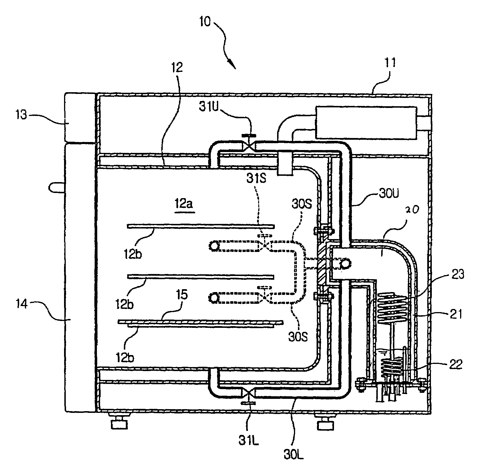
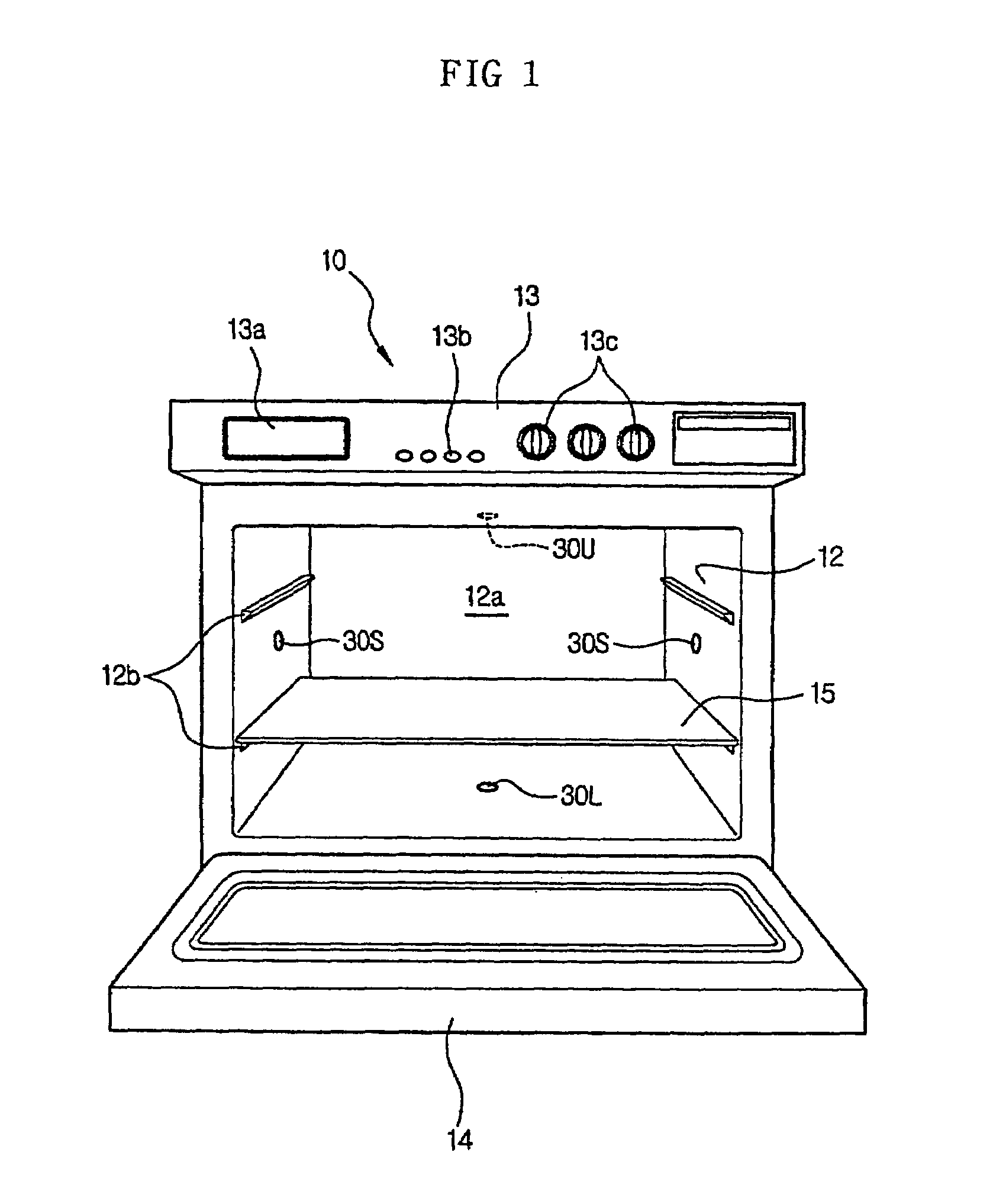
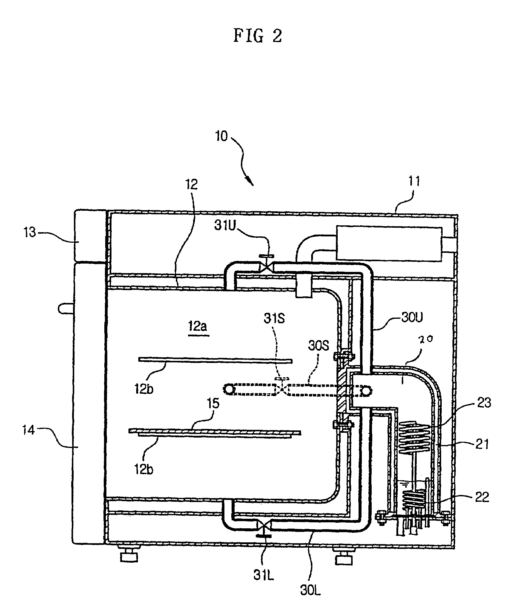
[0027]As shown in FIGS. 1 and 2, a steam oven according to a first embodiment of the present invention includes a cabinet 10 which forms an outer appearance of the steam oven and defines a cooking cavity 12a therein, and a steam generator 20 which generates overheated steam so as to supply the overheated steam into the cooking cavity 12a.

[0028]The cabinet 10 includes an outer casing 11 and an inner casing 12. The inner casing 12 is installed in the outer casing 11 spaced apart from the outer casing 11, and defines the cooking cavity 12a therein. A control unit 13, includes a display 13a to display an operational state of the steam oven thereon, various kinds of control bu...


PUM


Abstract

A steam oven which selectively heats food at desired locations includes a cabinet to define a cooking cavity therein, a steam generator to generate steam, a plurality of steam feed pipes to guide and supply the steam generated by the steam generator into the cooking cavity, including outlet ends placed at a plurality of predetermined positions in the cooking cavity so as to evenly distribute the steam into the cooking cavity, and a plurality of steam valves mounted at predetermined portions of the plurality of steam feed pipes. The plurality of steam valves independently control the plurality of steam feed pipes so as to change positions from which the steam is discharged into the cooking cavity. Therefore, the steam oven of the present invention cooks the food in desired directions by allowing the plurality of the steam valves to independently control the plurality of steam feed pipes.

Description

CROSS-REFERENCE TO RELATED APPLICATIONS[0001]This application claims the benefit of Korean Patent Application No. 2003-63003, filed Sep. 9, 2003 in the Korean Intellectual Property Office, the disclosure of which is incorporated herein by reference.BACKGROUND OF THE INVENTION[0002]1. Field of the Invention[0003]The present invention relates, in general, to steam ovens and, more particularly, to a steam oven to selectively heat food in desired directions.[0004]2. Description of the Related Art[0005]Generally, steam ovens are cooking apparatuses that cook food by generating steam and discharging the steam onto the food.[0006]Conventional steam ovens include a cabinet to define a cooking cavity therein, a steam generator to supply steam into the cooking cavity, and a steam feed pipe to guide and feed the steam generated from the steam generator to a lower portion of the cooking cavity so as to discharge the steam into the cooking cavity from the lower portion of the cooking cavity.[000...

Claims


Application Information

Patent Timeline
Patent Type & Authority Patents(United States)
IPC IPC(8): A21B1/08A47J27/16A47J27/04A21B3/04F24C1/00A47J39/00
CPCA21B3/04A47J27/16
Inventor KIM, CHEOL JIN
Owner SAMSUNG ELECTRONICS CO LTD
Why Eureka
Try Eureka