Rigging system for speaker cabinets

a speaker array and rigging technology, applied in the field of sound systems, can solve the problems of increasing difficulty, using spacers, and affecting so as to facilitate the movement of a portion and improve the sound quality of the sound system

Inactive Publication Date: 2007-08-28
ATLAS SOUND
View PDF22 Cites 43 Cited by
  • Summary
  • Abstract
  • Description
  • Claims
  • Application Information

AI Technical Summary

Benefits of technology

[0001]The present invention is directed to the field of sound systems. More particularly, the present invention is directed to a rigging system for...

Problems solved by technology

When sound systems are “built” in a large amphitheater or auditorium, the use of multiple speakers has the potential to create acoustical problems.
Use of spacers or shims is problematic, at best, and the need to move the speaker stack to accommodate such wedges increases the difficulty.
However, the movement of a stack of speaker is still an issue; the stack, whether ground mounted or suspended, must ...

Method used


Image

  • Rigging system for speaker cabinets
  • Rigging system for speaker cabinets
  • Rigging system for speaker cabinets

Examples


Embodiment Construction

)

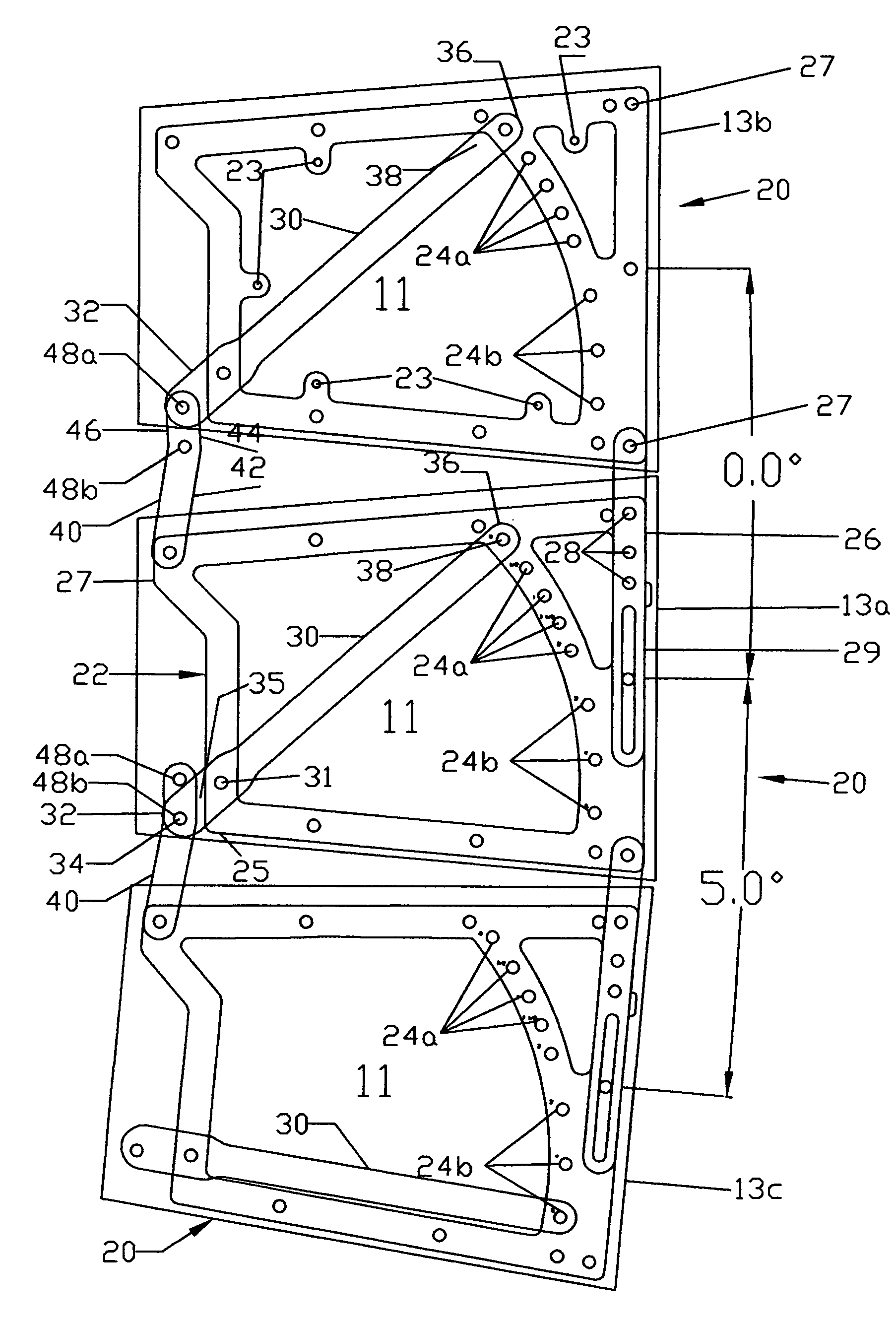
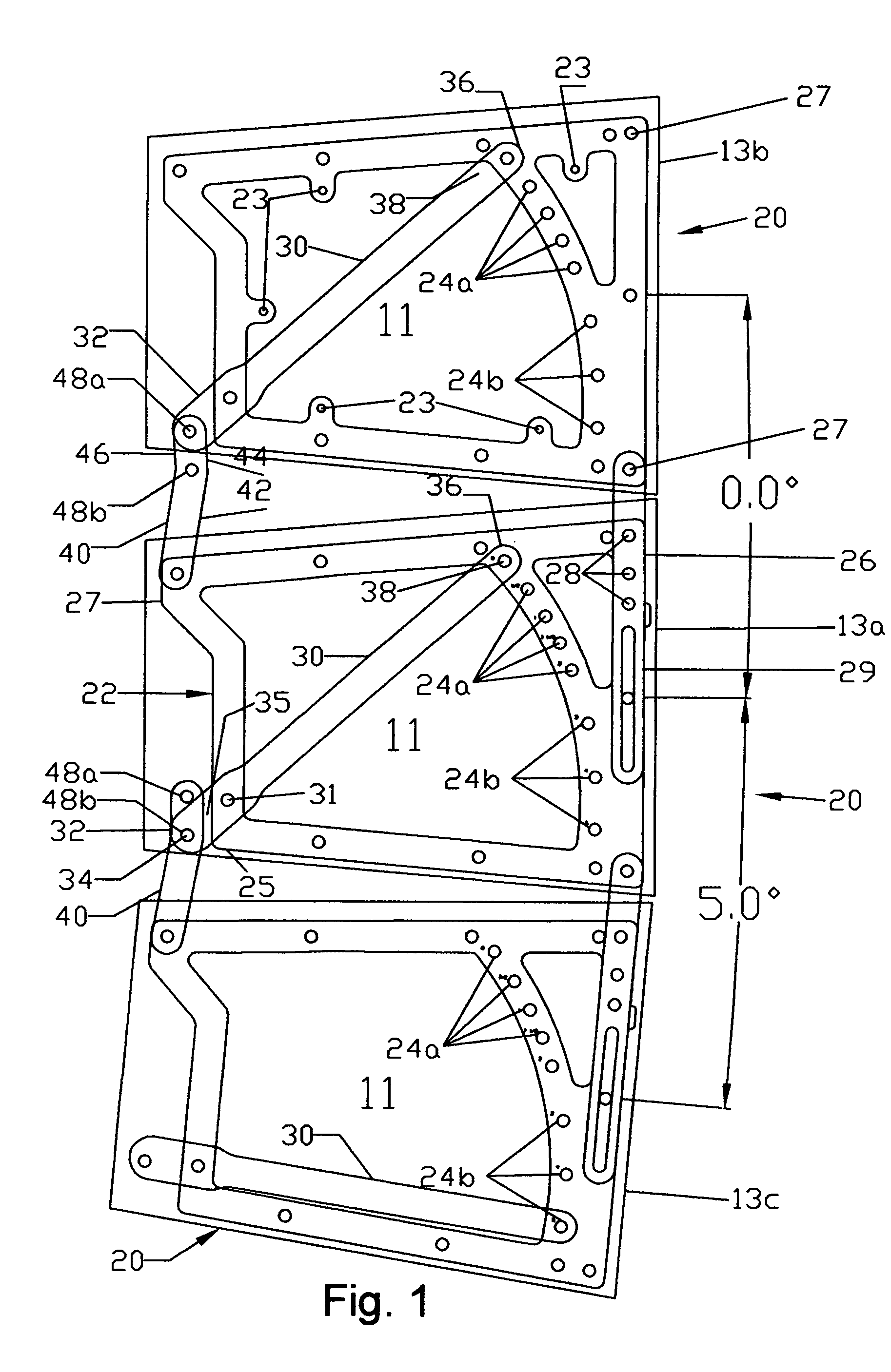
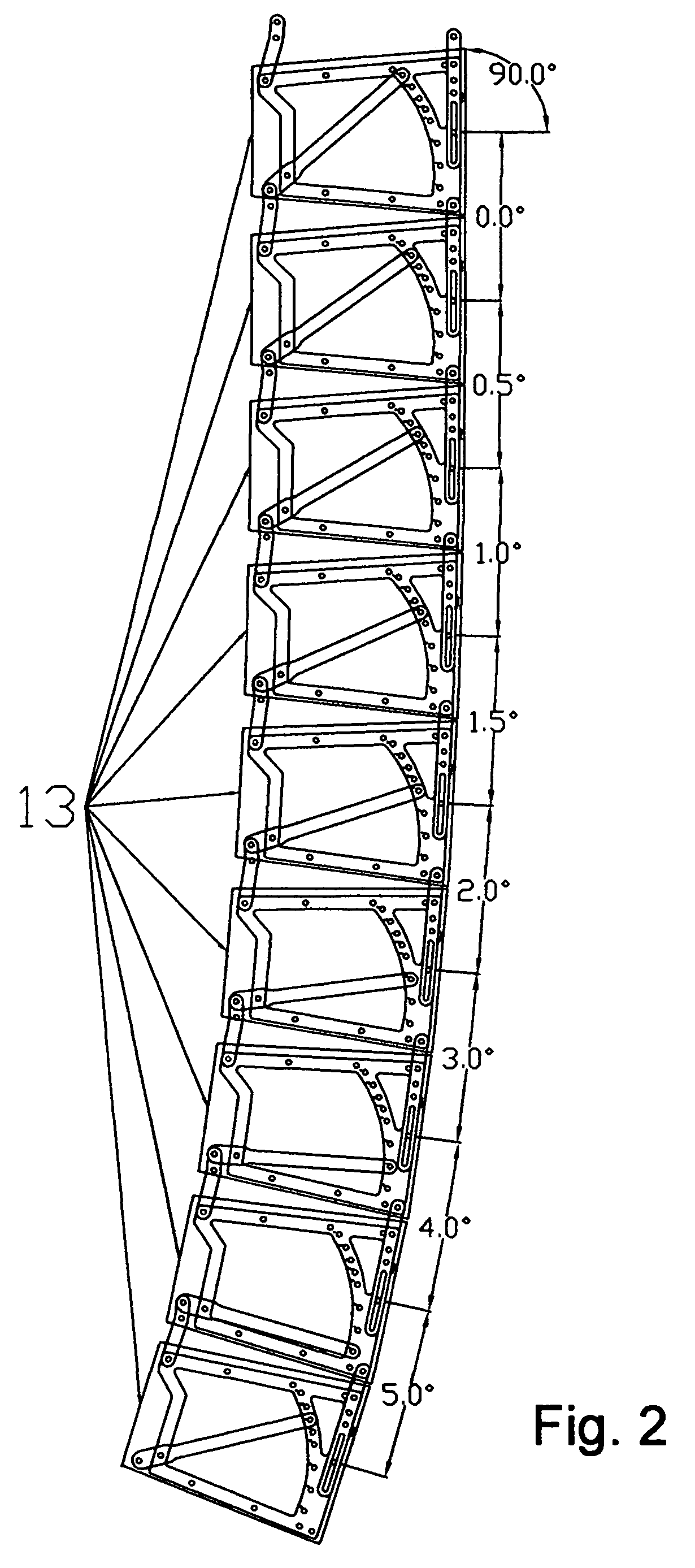
[0012]A first embodiment of the rigging system for cabinets of the present invention is depicted in FIGS. 1-4 generally at 20. While speaker stacks will more typically extend from between 6 and 12 speakers, three cabinets, first cabinet 13a, second cabinet 13b and third cabinet 13c, are shown here for purposes of explanation. As best seen in FIG. 1, rigging system 20 includes a generally rectangular bracket 22 that is attachable to the side panel 11 of a first speaker cabinet 13a by inserting hardened cap screws (not shown) through holes 23. A second bracket (not shown) which is a mirror image of bracket 22 is attached to the opposite side of speaker cabinet 13a. When adjustments to rigging system 20 are discussed herein, it will understood that adjustment will be made to both brackets 22 on each side of a speaker 13.

[0013]Bracket 22, which may actually more accurately be described as generally trapezoidal, has a plurality of arcuately spaced openings 24. Openings 24a are separated...


PUM


Abstract

A rigging system includes a lever arm permitting all speakers supported by the speaker whose rigging is adjusted to be angularly reoriented to focus the system, even out the coverage and fine tune the coverage. Multiple pivot attachment points for the moment arm are provided to enable an enhancement of the angular adjustment provided. A dozen or more angular positions can be provided for the lever arm to facilitate the trial-and-error method of optimizing the sound quality within the house.

Description

BACKGROUND AND SUMMARY OF THE INVENTION[0001]The present invention is directed to the field of sound systems. More particularly, the present invention is directed to a rigging system for forming speaker arrays which includes a lever arm which facilitates the movement of a portion of the array to improve sound quality of the sound system.[0002]When sound systems are “built” in a large amphitheater or auditorium, the use of multiple speakers has the potential to create acoustical problems. Speaker arrays are focused to provide even coverage in the audience area and fine tune the sound distribution, avoiding bouncing the sound off the ceiling and walls. The sound will be focused, directed, toward the rear of house with lesser amounts of concentrated sound energy aimed at the front of the house, due to the audience's proximity to the speakers.[0003]It is often the case that speakers are stacked 6, 8 or 12 or more, high. These stacks may be floor mounted or suspended from a ceiling brack...

Claims


Application Information

Patent Timeline
IPC IPC(8): E04B1/343A47B46/00H05K7/16
CPCH04R1/026
Inventor FARANDA, ANTHONY RCHASE, RICHARD P
Owner ATLAS SOUND
Why Eureka
Try Eureka