
Eyeglass frame with integral channel to receive decorative inserts

a technology of eyeglass frames and inserts, applied in the field of eyeglass frames, can solve the problem of inability to interchange the decorative designs of the temple frames, and achieve the effect of quick removal and replacemen

Inactive Publication Date: 2007-08-28
TABER JOHN A JACK
View PDF13 Cites 71 Cited by
  • Summary
  • Abstract
  • Description
  • Claims
  • Application Information

AI Technical Summary

Benefits of technology

[0009]Advantageously, the decorative insert is sized and shaped so as to closely fit the perimeter ridge rising above a central recessed surface. This feature of the invention protects the edges of the decorative insert from fraying and wear.
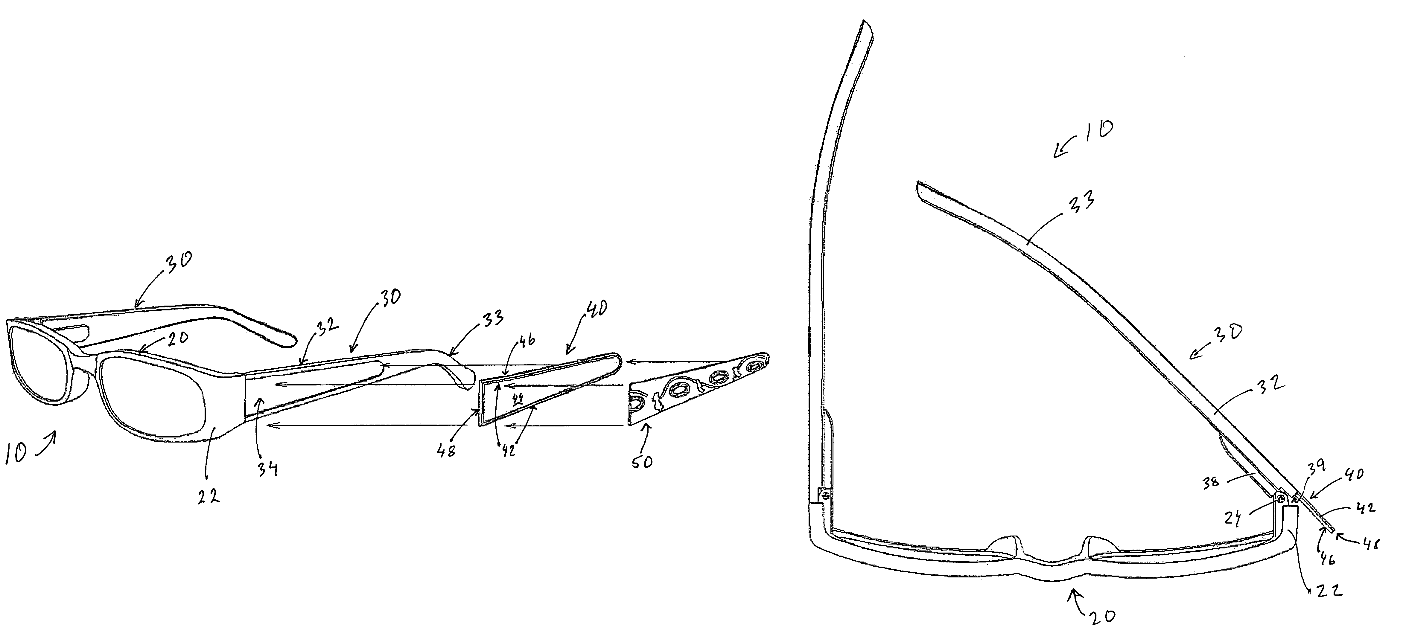
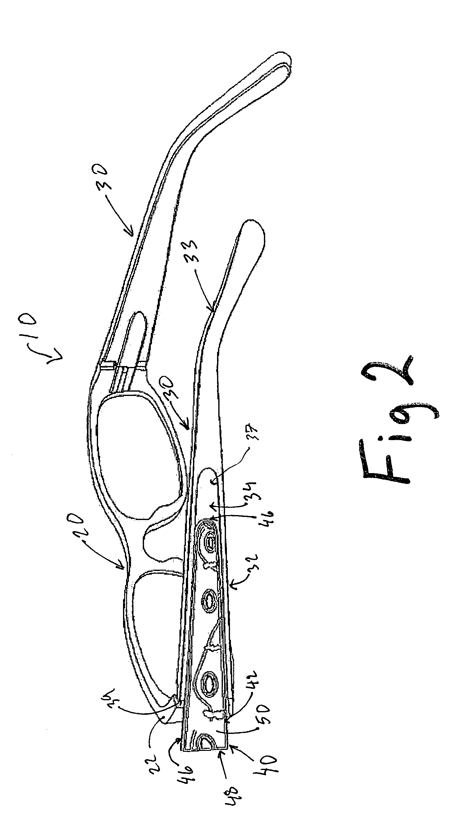
[0012]Advantageously, with the temple frame fully extended from the lens frame so as to be in a configuration for wearing by the user, the temple insert can not be removed from the channel nor are the temple end of the insert and proximal end of the temple frame visible. But, by simple rotation of the temple frame, the selected insert can be quickly removed and replaced in a just a few seconds and without the use of tools. This feature of the present invention provides a distinct advantage over the prior art methods of installing a decorative element.

Problems solved by technology

One disadvantage of these prior art eyeglass frames is the inability to interchange the decorative designs of the temple frames.

Method used


Image

  • Eyeglass frame with integral channel to receive decorative inserts
  • Eyeglass frame with integral channel to receive decorative inserts
  • Eyeglass frame with integral channel to receive decorative inserts

Examples


Embodiment Construction

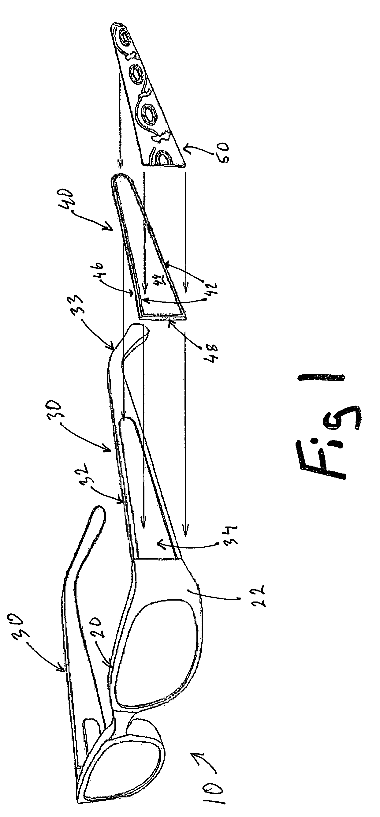
[0020]One embodiment of eyeglass frame of the present invention is shown in FIGS. 1-5. Referring to FIG. 1, an eyeglass frame 10 of the present invention is shown in an exploded view and includes a lens frame 20 rotably connected to a pair of temple frames 30. Temple frame 30 is adapted to receive a temple insert 40, which has a decorative insert 50 attached thereon. The lens frame 20 of the embodiment shown in FIG. 1 includes a lateral extension 22 attached via a hinge (not shown) to one temple frame 30. The temple frame 30 includes a temple bar 32 extending from the lateral extension 22 and terminating in an ear hook 33, which is adapted to conform to the ear of the user.

[0021]A channel 34 is disposed in the temple bar 32, as is shown in FIGS. 1 and 2. The channel 34 includes an end opening 35 disposed in the proximal end 39 of the temple frame 20 and further includes the side opening 37 disposed in the side of the temple bar 32. The channel 34 is adapted to receive a temple inser...


PUM


Abstract

A decorative eyeglass having a pair of temple frames adapted to receive an interchangeable temple insert with a decorative insert attached thereon. A flanged channel disposed in the temple bar of the temple frame is adapted to receive the temple insert through an end opening disposed in the proximal end of the temple frame. The temple insert includes a perimeter ridge rising above a central recessed surface adapted to receive the decorative insert and a flat temple end protecting the edges of the decorative insert from fraying and wear. The perimeter flanges of the temple insert prevent the temple insert from entering or exiting the channel via the side opening. Insertion and removal of the temple insert is accomplished by rotating the temple frame relative to the lens frame so as to expose the end opening. With the desired temple insert fully inserted into the channel, the temple frame may be rotated so as to block the end opening by the lens frame. A coordinated apparel system includes the eyeglass frame with a selected temple insert and decorative insert selected from a plurality of temple inserts each having a decorative insert displaying an ornamental feature wherein the decorative insert is selected such that the ornamental features of the decorative insert are matched and coordinated with the ornamental feature of a item of decorative apparel.

Description

BACKGROUND OF THE INVENTION[0001]The present invention relates generally to the field of eyeglasses worn for vision correction, for reduction of glare or for recreational activities. More particularly, this invention pertains to foldable eyeglass frames having decorative ornamentation displayed on the side pieces of the frame.[0002]It is known in the prior art to embellish such eyeglass frames by providing decorative elements on the side pieces, such side pieces herein termed temple frames. It is also known in the prior art to select eyeglass frames according to their decorative elements so as to match the decorative elements of other apparel worn by the user.[0003]As examples, U.S. Pat. No. 6,652,093 and PCT Publications WO 98 / 23994 and WO 97 / 44699 each describe an eyeglass frame structure comprising a decorative element of a temple frame that is mounted in a manner such that the decorative element can rotate with respect to the fixed parts of the temple frame from one position in ...

Claims


Application Information

Patent Timeline
IPC IPC(8): G02C11/02
CPCG02C11/02
Inventor TABER, JOHN A. JACK
Owner TABER JOHN A JACK
Learn More