Method and system for operating a racking system preferably in a dispatch unit

a technology of a racking system and a dispatch unit, which is applied in the directions of transportation and packaging, loading/unloading, storage devices, etc., can solve the problems of limited dispatch output and disadvantage of the rack serving system

Active Publication Date: 2007-08-28
KNAPP AG
View PDF33 Cites 67 Cited by
  • Summary
  • Abstract
  • Description
  • Claims
  • Application Information

AI Technical Summary

Benefits of technology

[0004]The object of the present invention is essentially to make the prior-art method and system more efficient and to correspondingly m...

Problems solved by technology

The limited dispatch output and inflexibil...

Method used


Image

  • Method and system for operating a racking system preferably in a dispatch unit
  • Method and system for operating a racking system preferably in a dispatch unit
  • Method and system for operating a racking system preferably in a dispatch unit

Examples


Embodiment Construction

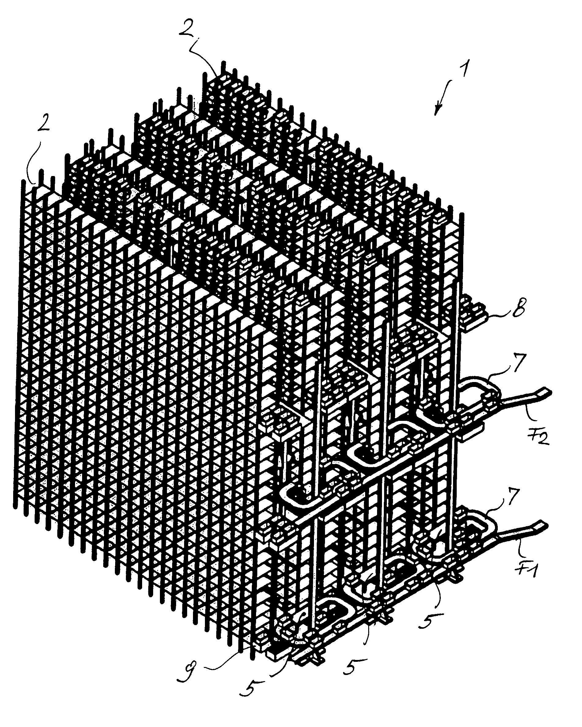
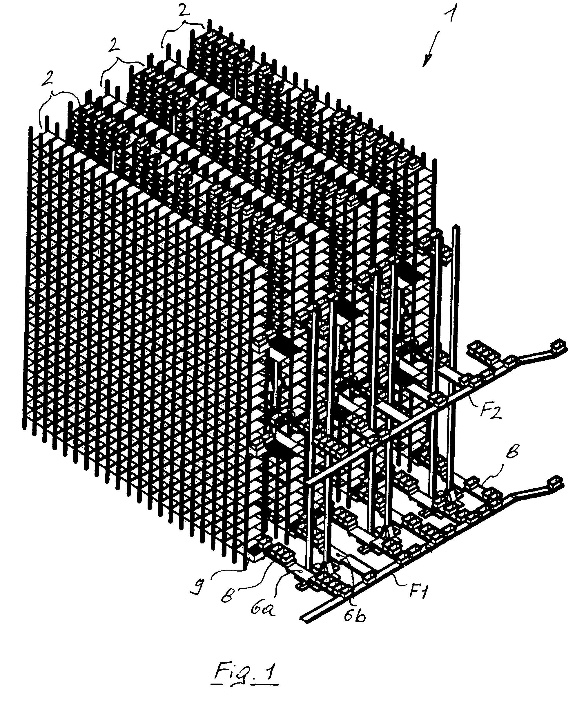
[0033]Referring to the drawings in particular, according to the drawings, the container storage area of a dispatch unit 1 comprises a composite rack 2 comprising three double racks in a parallel arrangement with longitudinally displaceable rack serving devices 4 according to FIGS. 5 and 6, which are arranged in the rack aisles 14.

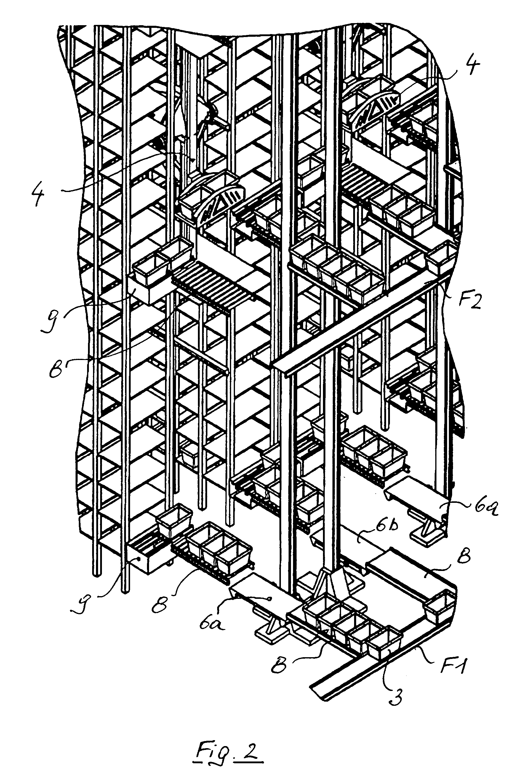
[0034]As can be best recognized from FIGS. 3, 4 as well as 9 and 10, a dedicated rack serving device 4 is associated with each rack aisle 14. The overall height of the rack is divided into three rack regions, which are arranged one above the other and comprise eight rack planes 13 arranged one above the other each, wherein each rack region has a dedicated, mechanically coupled, height-and length-adjustable rack serving device 4 as an independent and closed rack unit A, B and C.

[0035]The rack serving device 4 has an elevating chassis 10 and an elevating platform 11 of a small overall height essentially at the same height, the elevating chassis 10 and the ele...


PUM


Abstract

A method for operating a rack system preferably in a dispatch unit (1), with a rack (2) and an associated rack serving device for the storage and retrieval of containers (3), trays or the like to or from the rack. A rack region of the rack (2) has a plurality of rack planes (13) arranged one above the other and is served by a dedicated, mechanically coupled, height and length-adjustable rack serving device (4). In each track region embodied as an independent, closed rack unit (A, B, C), containers (3), trays or the like undergo interim storage in a buffer zone (P1, P2, P3) on the same level, are transferred for storage or retrieval and transported by an elevator (5; 6a, 6b) and/or a preferably horizontal transport connection (F1, F2) arranged in the region of the rack unit (A, B, C) at the same level, from or to a transport system or workplace outside the rack system.

Description

FIELD OF THE INVENTION[0001]The present invention pertains to a method and a system for operating a rack system preferably in a dispatch unit, with a rack and an associated rack serving device for the storage and retrieval of containers, trays or the like into or out of the rack.[0002]Whenever the term “container” is used below it shall not be defined in a limiting manner; the present invention rather also comprises systems in which other transport units, e.g., trays or pallets are used to store and transport the product to be dispatched.BACKGROUND OF THE INVENTION[0003]According to a known prior art, containers are removed from a container storage area and sent via a height-adjustable rack serving device, which can be displaced along the container storage area, to a central distribution system, which joins the container storage area. In particular, the rack serving device serves two opposite storage racks over the entire height of the rack (cf. DE 197 12 839 A1). The limited dispat...

Claims


Application Information

Patent Timeline
IPC IPC(8): B65G1/06B65G1/04B65G1/137
CPCB65G1/0407B65G1/1378
Inventor FREUDELSPERGER, KARL
Owner KNAPP AG
Why Eureka
Try Eureka