Press-contact connector

a technology of contact connector and connector, which is applied in the direction of contact member penetrating/cutting insulation/cable strand, coupling device connection, electrical apparatus, etc., can solve the problems of manual wiring trouble and inability to work with automation, and achieve the effect of ensuring the holding force of the wir

Active Publication Date: 2007-08-28
YAZAKI CORP
View PDF28 Cites 8 Cited by
  • Summary
  • Abstract
  • Description
  • Claims
  • Application Information

AI Technical Summary

Benefits of technology

[0013]The present invention has been made in consideration of the problems, and it is an object to provide a press-contact connector which can be made compatible for automation and can sufficiently hold wires.
[0018]Therefore, the press-contact connector can be made compatible for automation and can sufficiently hold wires, and can thus overcome the conventional problem that compatibility with automation is difficult.
[0020]According to the press-contact connector constructed in this manner, as wires are held in a bent state by cooperation of the claw portions of the retaining portions and the lances, the wires can be held reliably.
[0024]According to the press-contact connector constructed in this manner, as wires can be held bent by the bulging portions provided at the retaining portions, the wires can be held reliably.
[0026]According to the press-contact connector constructed in this manner, because the retaining portion has the bulging portion bulging in the press-contacting direction, the wire is bent toward the bulging portion to be connected to the press-contact blade. Accordingly, the wires can be held reliably.
[0029]The invention can overcome the conventional problem such that because of an inability to be made compatible for automation, wiring should be done manually, and brings about an effect that sufficient wire holding force can be secured.

Problems solved by technology

Because the press-contact connector 100 disclosed in Unexamined Japanese Patent Publication No. 2000-12109 should have wires inserted from the cable insertion holes 103 of the press-contact block 104, compatibility with automation is difficult, bringing about such an inconvenience that manual wiring is troublesome.

Method used


Image

  • Press-contact connector
  • Press-contact connector
  • Press-contact connector

Examples


first embodiment

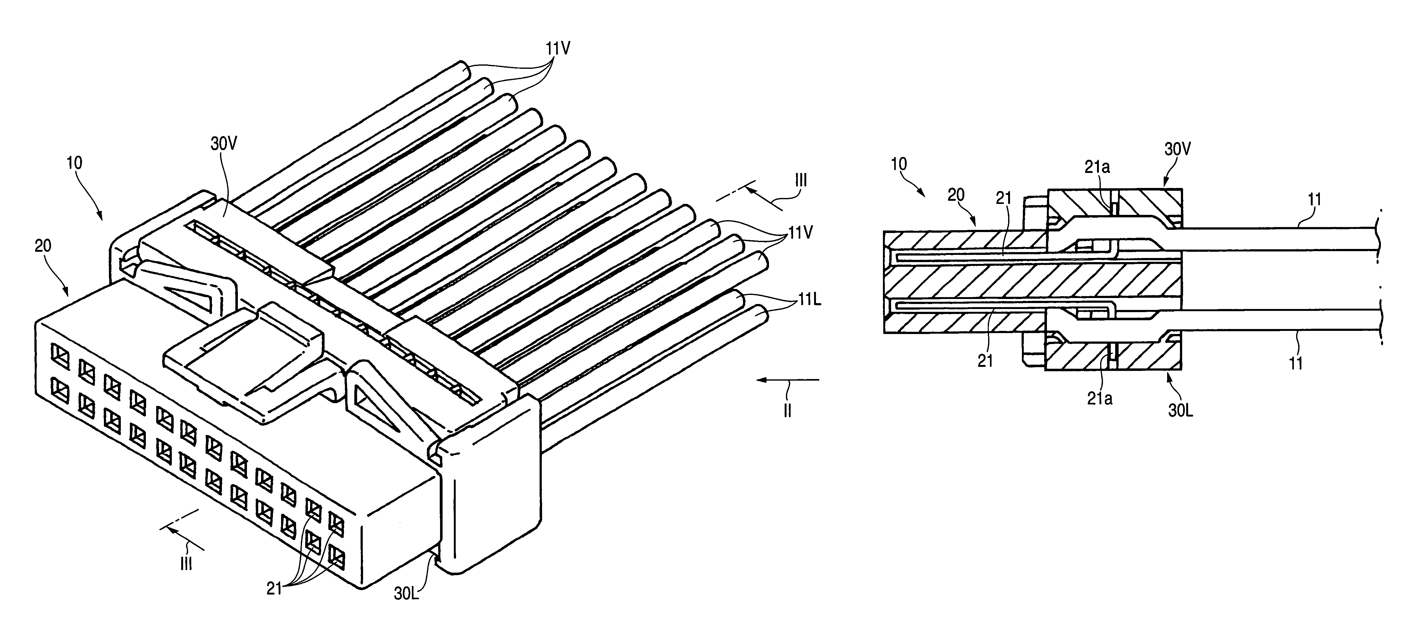
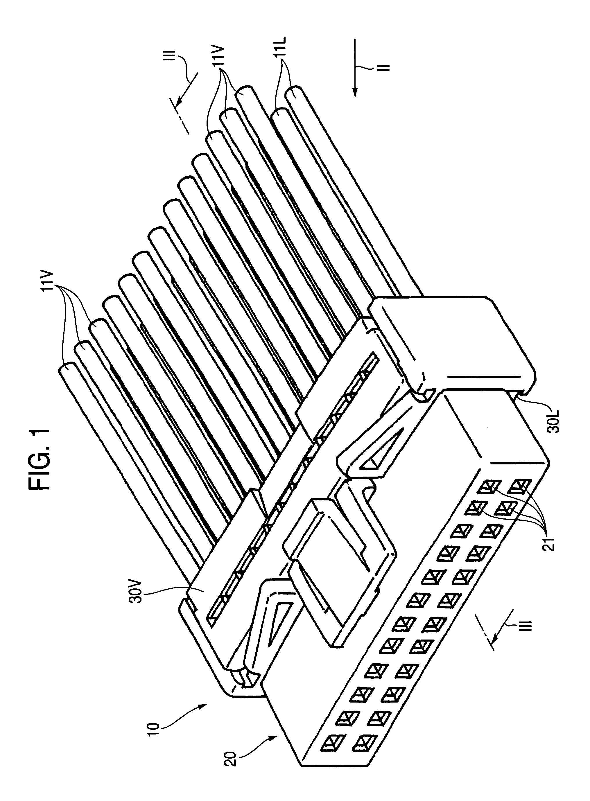
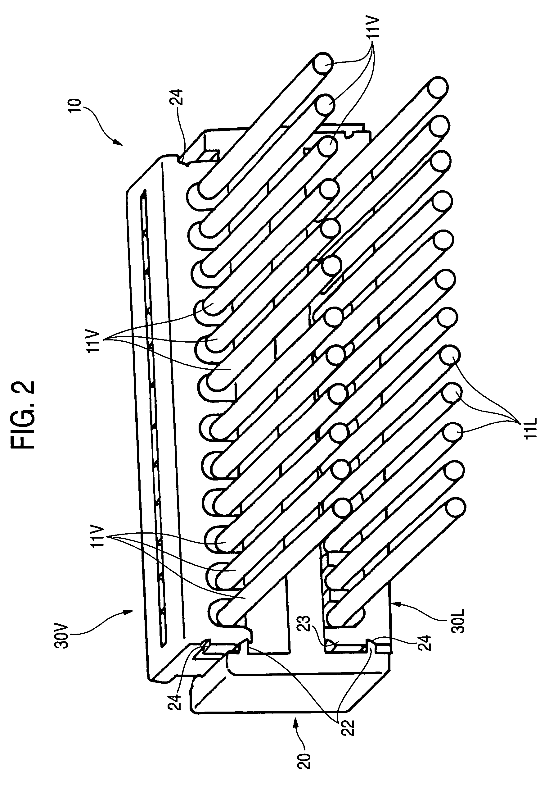
[0048]As shown in FIG. 1 and FIG. 2, a press-contact connector 10 according to the invention has a housing 20 as the first member, and a cover 30 as the second member to be attached to the housing 20. While it has a pair of upper and lower covers 30U and 30L, for example, either one will do.

[0049]A plurality of terminals 21 are retained in the housing 20, and a plurality of press-contact blades 21a connected to the respective terminals are provided protruding from a top surface 20a of the housing 20 (see FIG. 3). Here, the housing 20 is provided with two stages of upper and lower terminals 21 in association with the pair of upper and lower covers 30U and 30L.

[0050]The covers 30U and 30L hold plural wires 11 to be press-contacted to the respective press-contact blades 21a in an aligned state.

[0051]As shown in FIG. 2, there are provided temporary engagement lock member which temporarily locks the covers 30U and 30L at temporary engagement positions with respect to the housing 20 in su...

third embodiment

[0084]As shown in FIG. 12, a press-contact connector 60 according to the invention has a housing 61 as the first member and a housing 62 as the second member to which the housing 61 is attached. While it has a pair of upper and lower covers 62U and 62L, for example, either one will do.

[0085]As shown in FIG. 13, press-contact terminals 70 used for this press-contact connector 60 are female terminals and are provided, at the ends on one side, connection portions 71 for connection to other electrical parts or the like. The connection portion 71 has a pair of flexible connection pieces 71a and 71a which hold terminals, etc., of electrical parts or the like, for example, for conduction. A press-contact blade 72 for press-contacting with the wire 11 is provided at the other end of the press-contact terminal 70.

[0086]As shown in FIG. 14, the lower cover 62L has a rectangular cross section, and a retaining portion 31 where the wire 11 runs is provided at the upper portion, penetrating the f...


PUM


Abstract

A press-contact connector 10 has a first member 20 which accommodates a plurality of terminals 21 having press-contact blades 21a and a second member 30 which is attached to the first member 20 and holds a plurality of wires 11 in an aligned state. The second member 30 has a plurality of retaining portions 31 capable of retaining the wires 11 respectively, formed in an approximate U shape and arranged in parallel to one another. The retaining portion 31 has claw portions 33 which are provided at inner walls 32 to lock the wire 11 in such a way as to contact with a bottom portion 31a of the retaining portion 31, and lances 34 which are provided at serial directional ends of each retaining portion 31 to urge the wire 11 in the direction of the opening of the retaining portion 31 in a cross section. Since each wire 11 is held bent by the cooperation of the claw portions 33 with the lances 34, compatibility with automation is possible and the wires 11 can be held sufficiently.

Description

BACKGROUND OF THE INVENTION[0001]1. Field of the Invention[0002]The present invention relates to a press-contact connector which electrically connects wires to terminals by inserting press-contact blades into the wires.[0003]2. Related Art[0004]There have existed press-contact connectors for electrically press-connecting cables inserted into a press-contact block to press-contact portions of terminals as shown in Unexamined Japanese Patent Publication No. 2000-12109. As shown in FIG. 15, this press-contact connector 100 has a terminal block 102, which accommodates a plurality of terminals 101 for press-contacting individual cables to electrically conduct them, and a press-contact block 104 having cable insertion holes 103 for insertion of the cables and set in parallel to the terminal block 102 so that it can be relatively moved close to the terminal block 102 in translation.[0005]To facilitate the cable insertion, it includes inclination holding units 105, 106 and 107 capable of re...

Claims


Application Information

Patent Timeline
Patent Type & Authority Patents(United States)
IPC IPC(8): H01R4/24
CPCH01R4/242H01R13/112H01R13/506H01R12/675
Inventor YAMANASHI, MAKOTOMURO, TAKASHI
Owner YAZAKI CORP
Why Eureka
Try Eureka