A coupler

a coupler and coupler technology, applied in the field of couplers, can solve the problems of lack of engagement force, significant health and safety risk, and injury to peopl

Active Publication Date: 2012-07-26
DOHERTY ENGINEERED ATTACHMENTS
View PDF9 Cites 8 Cited by
  • Summary
  • Abstract
  • Description
  • Claims
  • Application Information

AI Technical Summary

Benefits of technology

[0067]However, in the preferred embodiment deliberate movement of the actuator can still move the locking mechanism to the release position thereby allowing the jaw to move.
[0068]This feature is useful in protecting against loss of engagement force which would otherwise result in the jaw releasing the pin causing the work attachment to disengage.

Problems solved by technology

However, if the actuator fails then the moveable jaw can move and release the pin.
This is referred to as lack of engagement force and provides a significant health and safety risk.
There have been a number of recent high profile accidents involving failures such as this causing injury to people.
Lack of engagement force is caused by failure of an actuator.
However, it is an inherent problem of this type of coupler that this must be inverted to enable the jaw to release the pin.
This means that it can be a time consuming and awkward process to release the work attachment from the coupler.
In addition, relying on gravity to move the locking member means that the system is not fail safe.
For instance, dirt or debris may hinder movement of the locking member and prevent securing and / or releasing the jaw.
Yet a further failing of the available couplers is that they are generally configured to work attachments having a predetermined pin separation.
Therefore the couplers are not able to be used with different work attachments where the pin spacing varies.
This can be a significant limitation on the available couplers.
An additional limitation to the effectiveness of similar devices is that they are designed specifically for use with a fixed coupler.
Any angle less than perpendicular will reduce the effectiveness of a gravity operated locking member.

Method used


Image

  • A coupler
  • A coupler
  • A coupler

Examples


Embodiment Construction

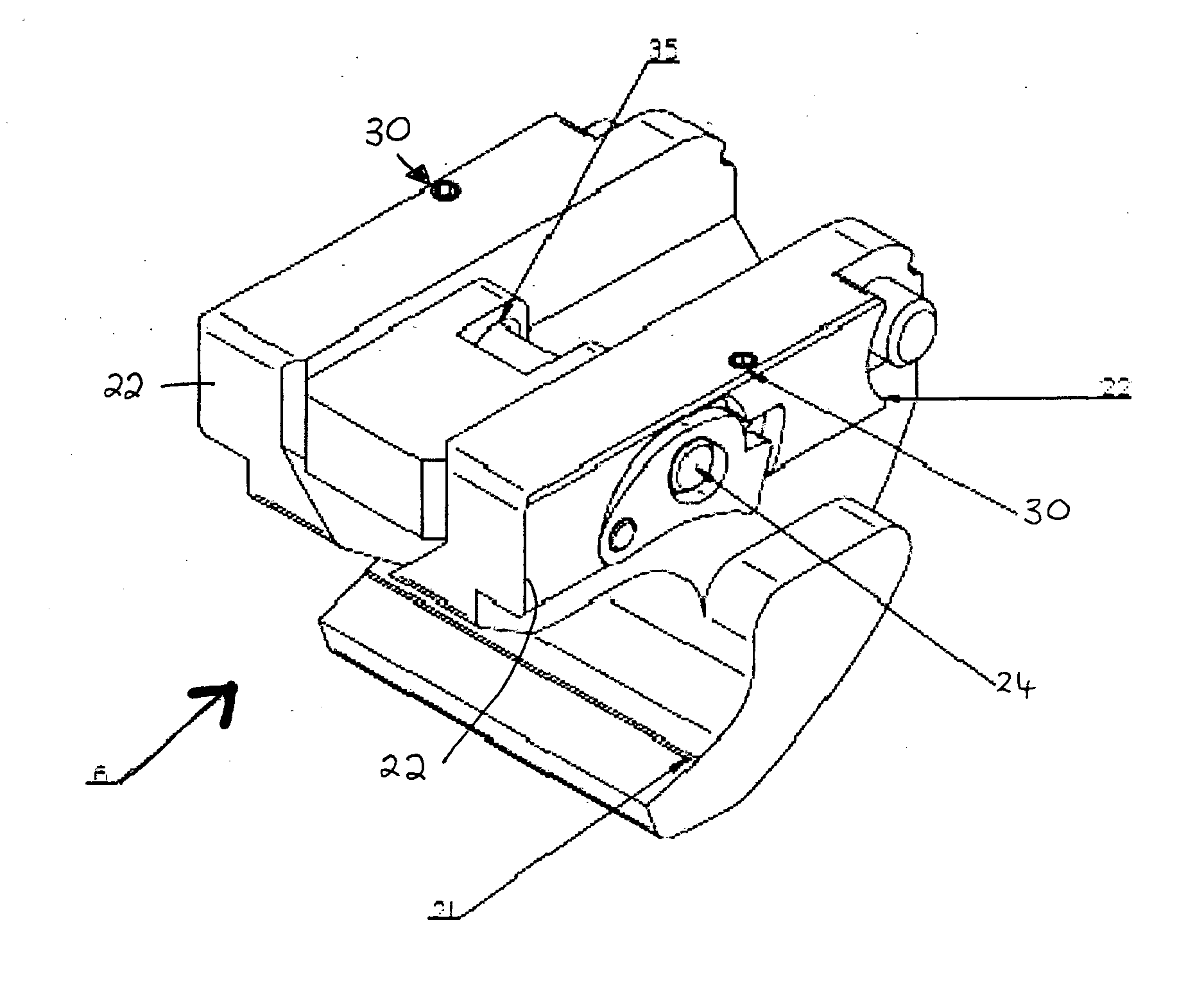
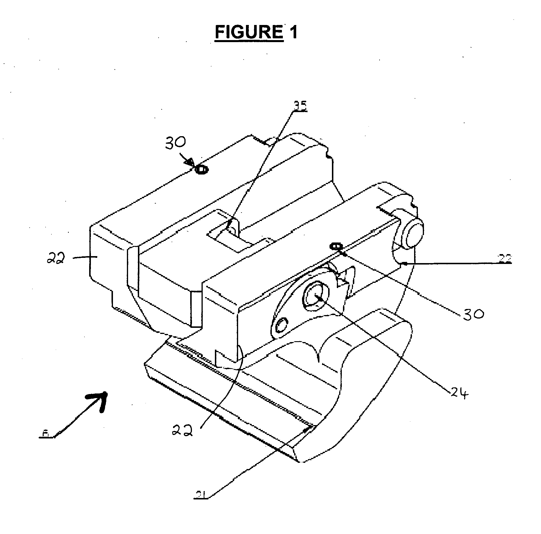
[0086]The present invention provides an improved coupler 1. The aspects of the coupler 1 will be described by reference to its components in the order in which they are assembled.

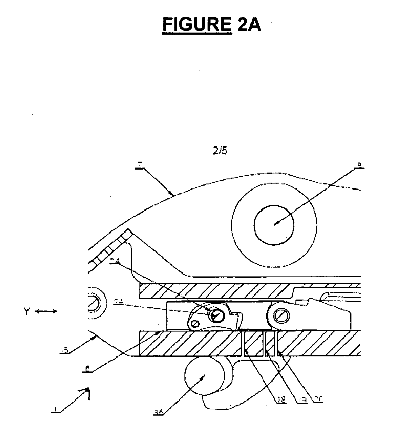
[0087]A body 2 houses the components of the coupler 1. The body 2 has side walls and end walls 4. The walls 3, 4 define a cavity 5 to receive a slide 6.

[0088]Flanges 7, 8 on the body 2 have apertures 9, 10 forming part of a quick hitch (not shown). The quick hitch facilitates securing the coupler 1 to an excavator (not shown). This should be understood by those skilled in the art.

[0089]A first end 11 of the body 2 is formed to provide a first jaw 12. The first jaw 12 may include a locking system to secure a pin therein. The locking system is not shown in order to simplify the Figures. However it could be any known or yet to be developed locking system.

[0090]A second end 13 of the body 2 has an aperture 14 into the cavity 5.

[0091]The inside of side walls 2 have channels 15 one of which is shown in FIGS. 2A a...


PUM

PropertyMeasurementUnit
angleaaaaaaaaaa
loss of engagement forceaaaaaaaaaa
forceaaaaaaaaaa

Abstract

There is provided a locking mechanism to secure a coupler's jaw, and a coupler incorporating the locking mechanism.

Description

PRIORITY CLAIM[0001]This application is a United States National Stage Application claiming the benefit of priority under 35 U.S.C. 371 from International Patent Application No. PCT / NZ2010 / 000192 filed Sep. 29, 2010, which claims the benefit of priority from New Zealand Patent Application Serial No. 579987 filed Sep. 29, 2009, the entire contents of which are herein incorporated by reference.TECHNICAL FIELD[0002]The present invention relates to a coupler.BACKGROUND ART[0003]A coupler is a device used to secure a work attachment to a work vehicle. They generally have jaws that receive pins on the work attachment.[0004]At least one of the jaws is moved by an actuator. This allows the jaws to engage and release the pins thereby securing and releasing the work attachment to the coupler as required.[0005]The actuator applies a driving or engagement force to the moveable jaw to retain the pin therein. Generally another jaw of the coupler faces in the opposite direction to the moveable jaw...

Claims


Application Information

Patent Timeline
Patent Type & Authority Applications(United States)
IPC IPC(8): F16B21/00B23P11/00
CPCE02F3/3618E02F3/3622Y10T403/591E02F3/3663Y10T29/49826E02F3/365E02F3/3659E02F3/3627Y10T403/593
Inventor DOHERTY, PAUL JAMESDOHERTY, JEREMY GLEN
Owner DOHERTY ENGINEERED ATTACHMENTS
Why Eureka
Try Eureka