Tendon fixation plate

Active Publication Date: 2017-06-29
INOVEDIS GMBH
View PDF4 Cites 7 Cited by
  • Summary
  • Abstract
  • Description
  • Claims
  • Application Information

AI Technical Summary

Benefits of technology

[0005]The object of the present invention is, therefore, to make available a possibility for securing tissue to bone in the context of

Problems solved by technology

A disadvantage of this is, in particular, that the fixation of the tendon takes more time and therefore entails increased costs.
It is also a disadvantage that the fixation of the tendon may not have sufficient stability, for example, on account of incorrect proc

Method used


Image

  • Tendon fixation plate
  • Tendon fixation plate
  • Tendon fixation plate

Examples


Embodiment Construction

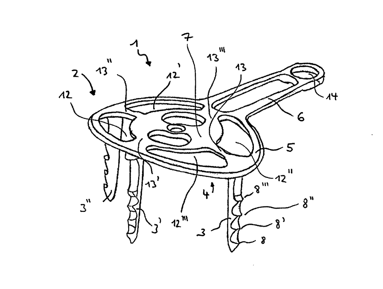
[0057]FIG. 1 shows a perspective view of an implant 1 according to the present invention. With the clamping surface 2 of the implant 1, tissue, e.g. tendinous tissue, is secured on a bone (see FIG. 7 and FIG. 8). The clamping surface 2 has an at least partially round circumference. Moreover, the clamping surface 2 is at least partially curved. The clamping surface 2 forms a plane.

[0058]The implant 1 comprises a clamping surface 2 and three securing members 3, 3′, 3″, which are each formed integrally on the clamping surface 2. The view shows that the securing member 3, 3′, 3″ are integrally formed on an underside 4 of the clamping surface 2. The securing member 3, 3′, 3″ thus have a conical shape at their side directed away from the clamping surface 2. In this way, the securing member 3, 3′, 3″ can be introduced particularly effectively into a tissue or into a bone. The view moreover shows that the securing members 3, 3′, 3″ comprise barbs 8, 8′, 8″ and 8′″. These are provided in ord...


PUM


Abstract

An implant for planar connection of tissue to bone is proposed, wherein the implant including a clamping surface and at least three securing members connected to the clamping surface, and wherein the clamping surface comprises an outer edge and an inner edge, wherein the outer edge is connected at least partially to the inner edge at least partially by at least one connecting web, and/or the clamping surface comprises an outer edge and at least one opening arranged within the clamping surface, which opening is connected by at least one connecting web at least to a partial area of the outer edge of the clamping surface.

Description

[0001]This application claims the benefit under 35 USC §119(a)-(d) of German Application No. 10 2015 122 730.4 filed Dec. 23, 2015, the entirety of which is incorporated herein by reference.FIELD OF THE INVENTION[0002]The present invention relates to an implant for planar connection of tissue to bone, and a system for connecting tissue to bone, comprising at least one implant and at least one tool.BACKGROUND OF THE INVENTION[0003]Various circumstances can lead to a surgical intervention having to be performed in order to fix and reconstruct torn tissues, e.g. tendinous tissue. In this regard, it is known from the prior art that, in order to reconstruct a tendon for example, the torn-off end of the latter is fixed to the bone by means of an implant. The terms anchor and bone anchor are also commonly used by a person skilled in the art for such an implant. For example, an anchor of this kind is disclosed in EP 2 581 046 A1. Such an anchor is usually driven into the bone for securing p...

Claims


Application Information

Patent Timeline
IPC IPC(8): A61F2/08A61B17/064
CPCA61F2/0811A61B17/0642A61F2002/0817A61B2017/0641A61F2002/0858A61F2002/0888A61F2220/0016A61F2002/0852A61B17/808A61B17/8085A61B17/809A61B17/846A61F2002/0829
Inventor FLOESS, LUKASOBLAK, PETERWELTE, STEFAN
Owner INOVEDIS GMBH
Why Eureka
Try Eureka