
Method for cleaning combustion devices

a technology for combustion devices and cleaning methods, applied in the direction of steam boiler components, hollow article cleaning, combustion treatment, etc., can solve the problem of exceedingly short dwell time of at least partially gaseous explosive components or of mixtures in hot ambient conditions

Inactive Publication Date: 2005-08-30
BANG & CLEAN
View PDF5 Cites 24 Cited by
  • Summary
  • Abstract
  • Description
  • Claims
  • Application Information

AI Technical Summary

Benefits of technology

[0008]The present invention is directed toward creating a method and device for cleaning of combustion installations or vessels contaminated with dirt and slag wherein the installation does not have to be shutdown during the cleaning operation. The present invention is further directed toward a method and device wherein the installation is in a clean condition again in a short time, and in which any endangering of personnel and of installation components during the cleaning process is minimised.

Problems solved by technology

This, in particular, results from the exceedingly short dwell time of the at least partially gaseous explosive components or of the mixture in the hot ambient.

Method used


Image

  • Method for cleaning combustion devices
  • Method for cleaning combustion devices
  • Method for cleaning combustion devices

Examples


Embodiment Construction

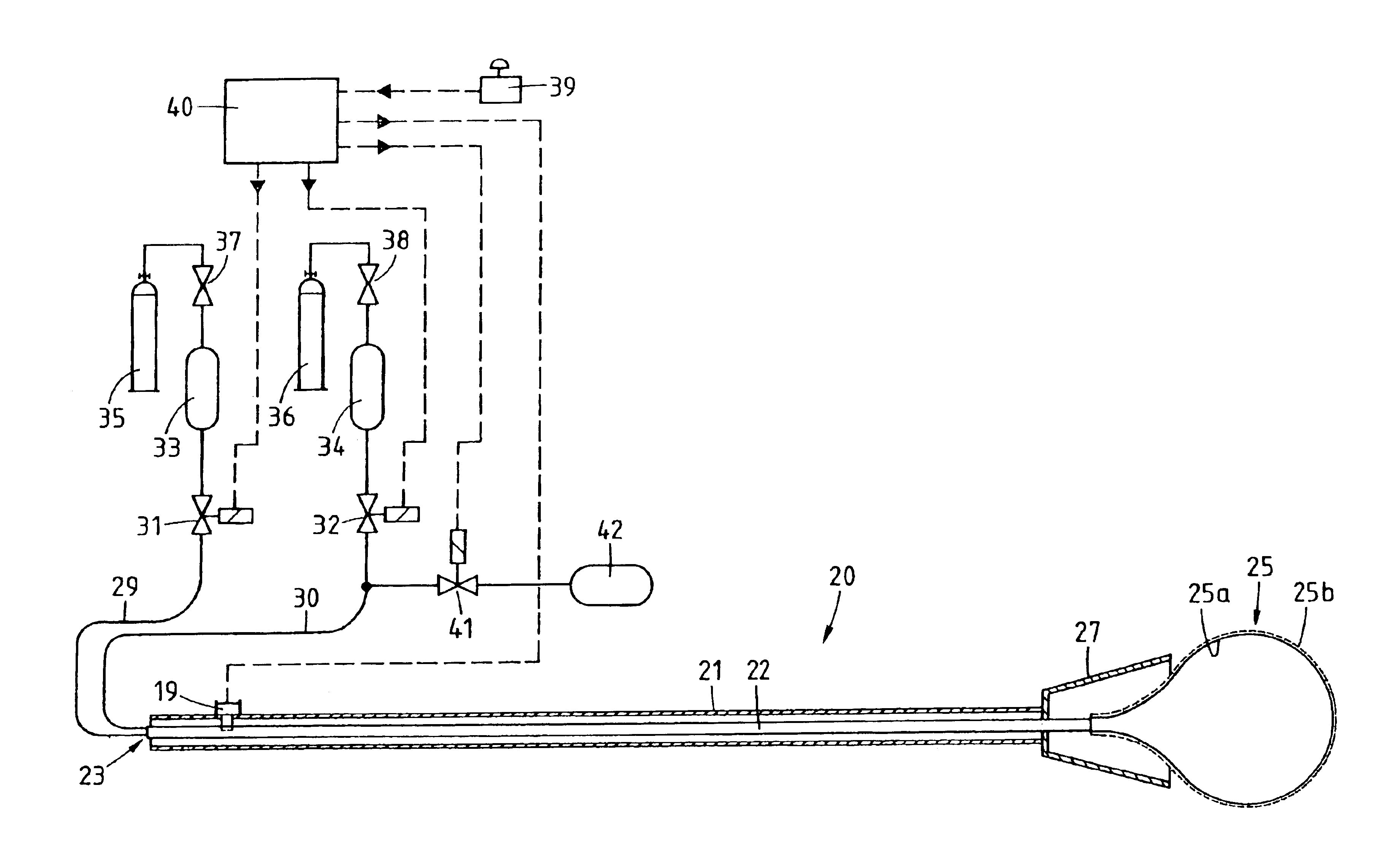
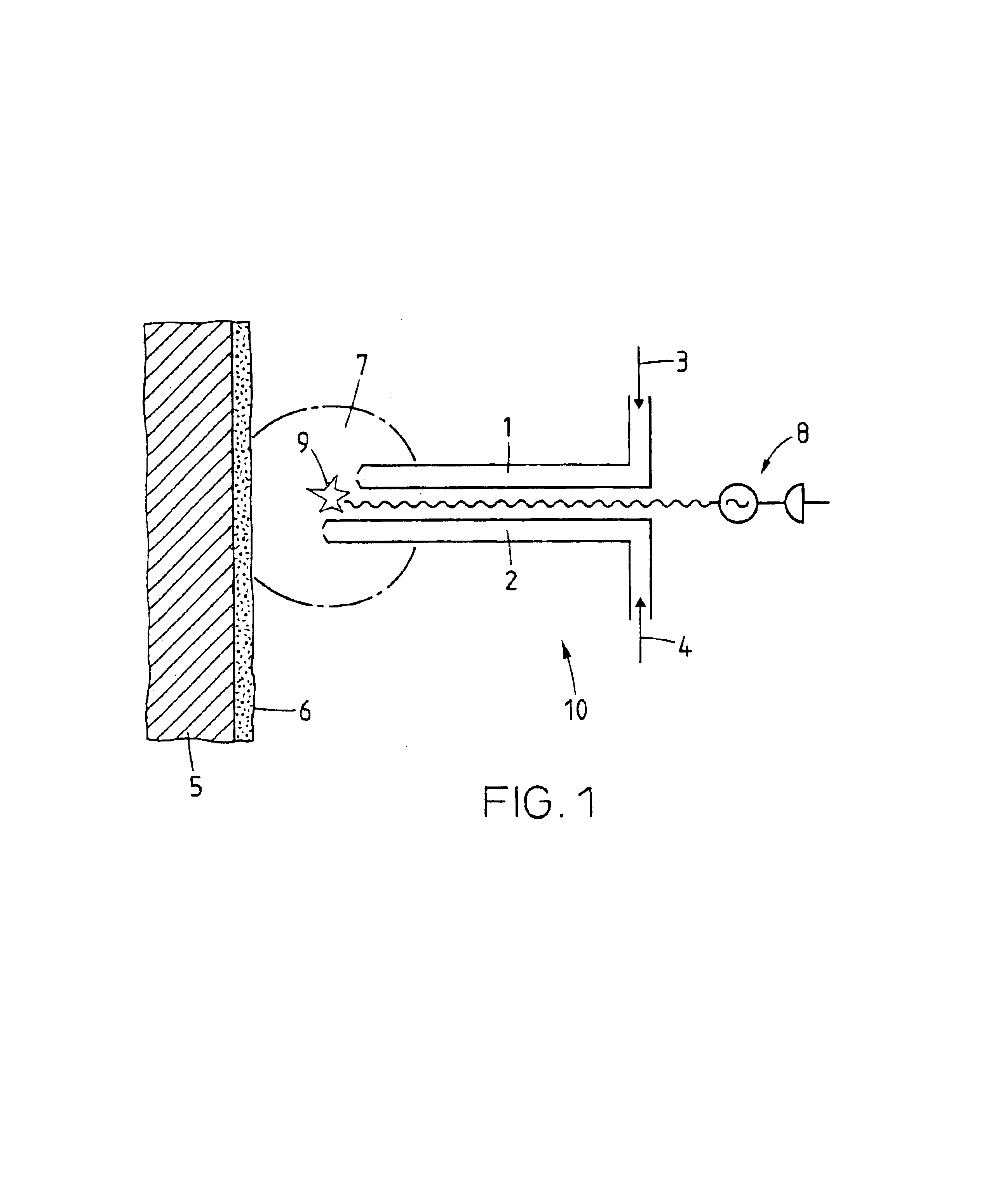
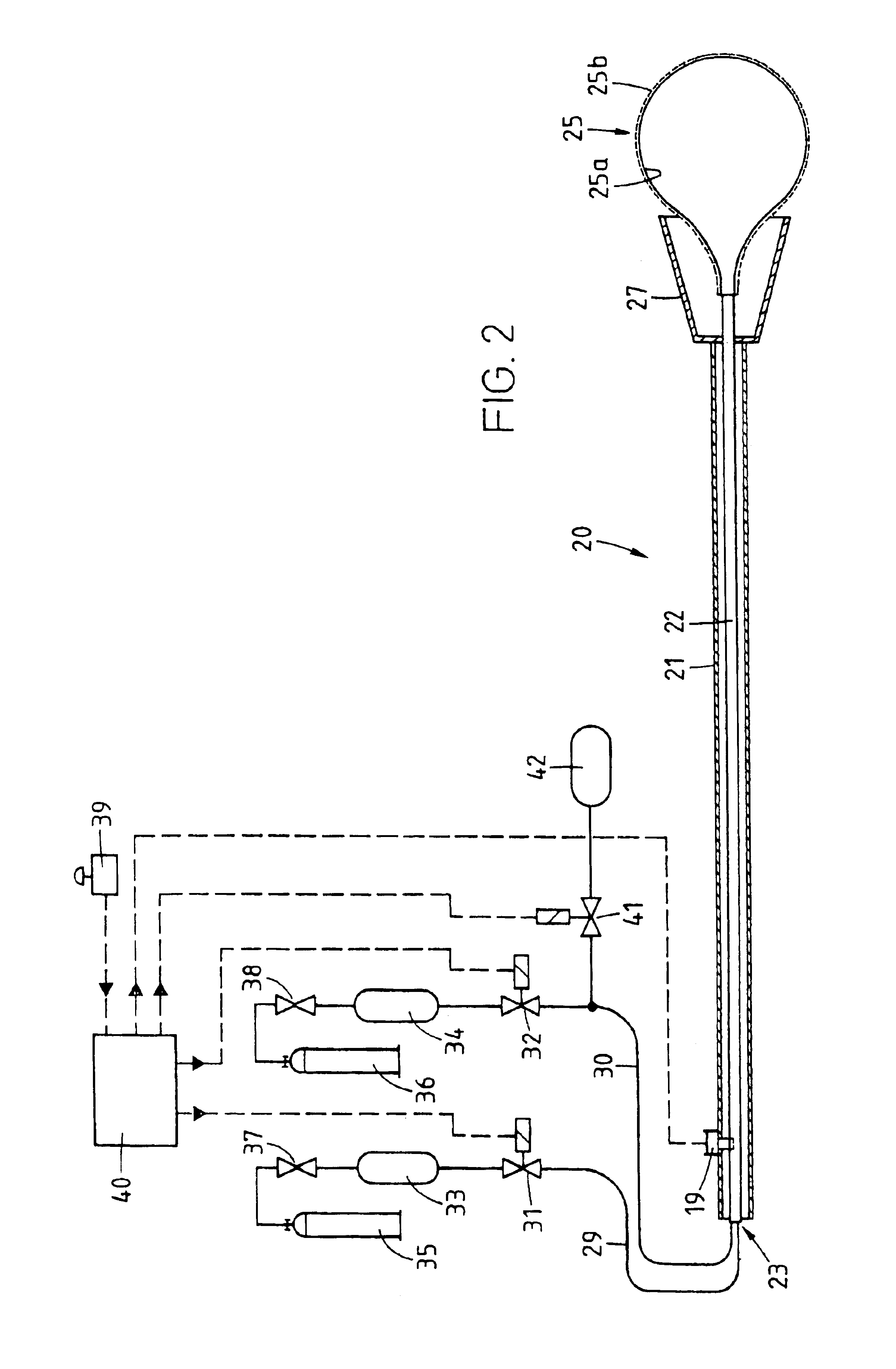
[0037]In FIG. 1, a device 10 for carrying-out the cleaning process according to the invention is illustrated. The device 10 includes pipe-like supply lines 1, 2 through which, preferably after their positioning, different gases, such as oxygen 3 and ethane 4, but also liquid fuels or oxidising agents are conducted to the proximity of the wall 5 to be cleaned. The gases 3, 4 and / or liquids in the zone of the wall contaminated with dirt 6 form an explosive mixture 7. By means of an ignition device 8, which is capable of being controlled and actuated from outside the vessel or installation to be cleaned, the explosive mixture 7 is ignited, for example, by the generation of an ignition spark 9. An ignition device located in the zone of the gas mixture 7, for example, on the supply lines 1, 2, may also trigger the explosion. The supply lines 1, 2 and the ignition device 8, here are designed such that the ignition spark 9 does not come to be situated directly in front of the end of a supp...


PUM


Abstract

An on-line method and a device for cleaning of contamination such as caking or slag deposits from surfaces in vessels and combustion installations by means of blasting technology. An explosive gas mixture is made to detonate in the proximity of the deposits and thereby clean the deposits from the surfaces.

Description

BACKGROUND OF THE INVENTION[0001]1. Field of the Invention[0002]The invention generally relates to a method and device for cleaning vessels contaminated with dirt, such as slag or ashes, and, more particularly, toward a method and device for the on-line blast cleaning of combustion installations.[0003]2. Description of Related Art[0004]Heating surfaces in waste incineration plants and coal-fired boilers are subject to contamination with dirt. The dirt normally has inorganic compositions and is typically produced by deposits of ash particles on the walls. Areas in the zone of high flue gas temperatures are in most instances very hard because they remain stuck to the walls either in molten form, or melted on form, or else are stuck together on the wall by substances melting or condensing at lower temperatures, when these solidify on the colder boiler wall. Coatings of this kind can only be removed with difficulty and unsatisfactorily by known cleaning methods. This leads to the conseq...

Claims


Application Information

Patent Timeline
Patent Type & Authority Patents(United States)
IPC IPC(8): B08B7/00F27D23/00F27D23/02F22B37/18F23H15/00F23J3/00F27DF27D1/16F27D25/00F28G1/00
CPCF27D25/006B08B7/0007B08B9/08F23J1/00
Inventor RUEGG, HANS
Owner BANG & CLEAN
Learn More