
Adjustable support

a technology of adjustable support and support plate, which is applied in the direction of machine support, instruments, manufacturing tools, etc., can solve the problems of not providing parallel planes between the mobile device and the target artwork, prior art stands, tripods, props that do not provide parallel planes, etc., and achieves the effect of large surface contact area

Inactive Publication Date: 2015-07-02
CHOW KENNETH H
View PDF13 Cites 9 Cited by
  • Summary
  • Abstract
  • Description
  • Claims
  • Application Information

AI Technical Summary

Benefits of technology

The patent text describes a stand that can hold a mobile electronic device with a camera at a certain angle over a surface. The stand includes a shelf, a dowel rod, and a base. The shelf can hold the device with the camera pointed downward and has a hole in it for the rod to slide through. The rod is inserted into the hole and becomes secure by friction. The shelf can pivot around the rod, so it stays securely in place. The base attaches to the rod and keeps the stand stable on the surface. The stand can also have a hinge with a leaf that can adjust the angle of the rod, allowing the shelf to be at different levels. Overall, the stand provides a way to hold a mobile device with a camera at a certain angle over a surface without obstructing the surface.

Problems solved by technology

Often it is tiring and problematic and produces inconsistent results.
Prior art stands, tripods, and props do not provide parallel planes between the mobile device and the target artwork.
Those that may provide parallel planes are not adjustable for height, have the encumbrance of an obstructed view from the camera, or just very expensive, bulky and heavy.
If the camera is skewed (i.e., not parallel) with respect to the target artwork, the target artwork may have a diminishing perspective view which may be undesirable.
Additionally, both hands are often preoccupied in holding the camera-equipped device as motionless as possible in trying to avoid blurred images.

Method used


Image

  • Adjustable support
  • Adjustable support
  • Adjustable support

Examples


Embodiment Construction

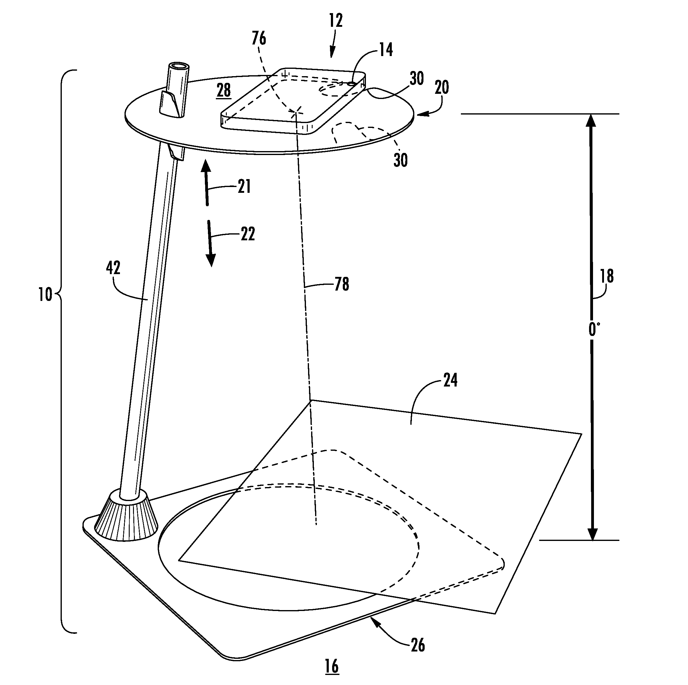
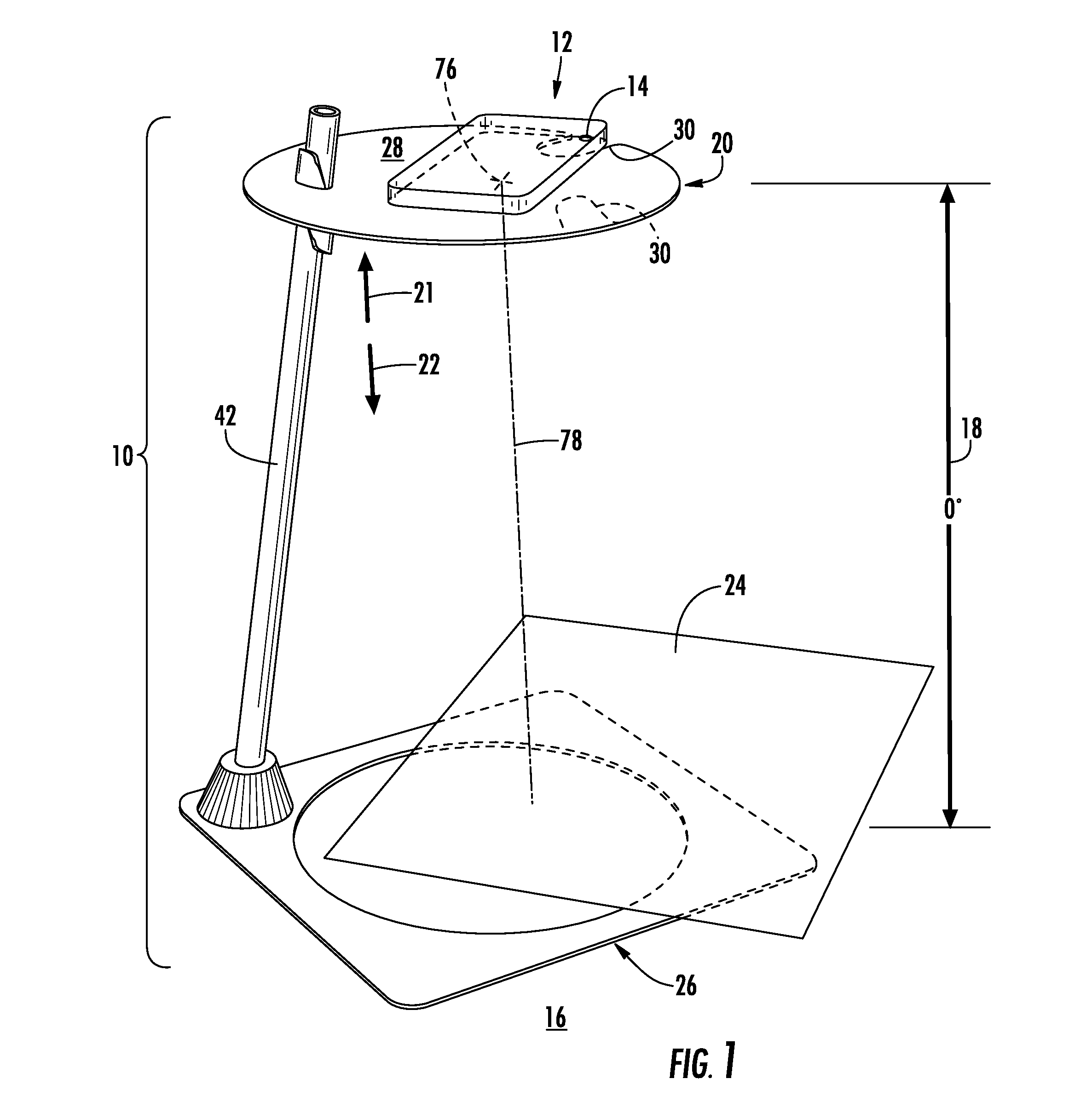
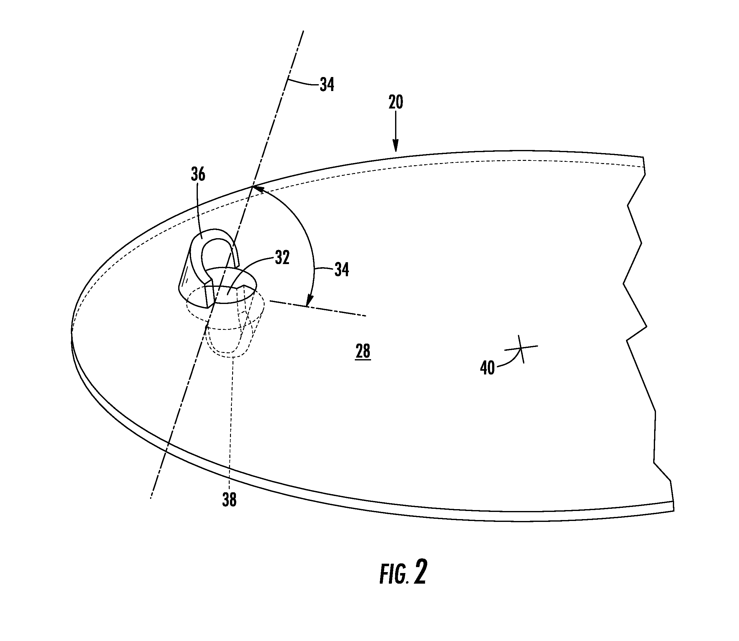
[0046]A stand 10 for holding a mobile electronic device 12 having a camera 14 above a support surface 16 at a particular angle 18 is shown. Moreover, a shelf 20 of the stand 10 may be vertically adjusted up 21 or down 22 to bring the camera 14 of the mobile electronic device 12 closer to or further away from an object 24 to be photographed. Regardless of the actual height of the shelf 20 above the support surface 16, the angle 18 can remain the same due to predetermined deflection. In this manner, the angular relationship between the camera 14 of the electronic device 12 and the target object 24 remains the same within a predetermined range of distances between the camera 14 of the electronic device and the target object 24. Also, the user need not balance the mobile electronic device 12 or try to maintain steadiness of the mobile electronic device 12 as the user takes a photograph of the object to be photographed 24 with the camera 14 of the mobile electronic device 12.

[0047]Referr...


PUM

PropertyMeasurementUnit
Angleaaaaaaaaaa
Diameteraaaaaaaaaa
Areaaaaaaaaaaa

Abstract

A stand for positioning a mobile electronic device with a built-in camera to an object supported on a support surface is shown. The space below the lens of the camera becomes unobstructed by the stand. The position of the mobile electronic device may be raised or lowered. A shelf upon which the mobile electronic device is supported may have through hole that receives a dowel rod. The dowel rod may have a hinged connection at the base. The dowel rod and the through hole may be in frictional engagement to each other for positioning the shelf to the object to be photographed or imaged. In order to raise or lower the shelf, the frictional engagement between the through hole of the shelf and the dowel rod may be disengaged then when the proper vertical position of the shelf is achieved, frictional engagement therebetween is reestablished. In order to adjust the level of the shelf, the angle established by the hinged connection may be changed by hand without the use of separate tools.

Description

CROSS-REFERENCE TO RELATED APPLICATIONS[0001]This application claims the benefits of Provisional Patent Application Ser. Nos. 61 / 923,194 and 61 / 923,201, filed on Jan. 2, 2014, the entire contents of which are expressly incorporated herein by reference.STATEMENT RE: FEDERALLY SPONSORED RESEARCH / DEVELOPMENT[0002]Not ApplicableBACKGROUND[0003]Various embodiments and aspects described herein relate to a stand for positioning a mobile electronic device with a built-in camera to an object being imaged or photographed.[0004]Camera equipped computers and phones are fast growing in use. IPhones, iPads, Samsung Galaxies and similar mobile electronic devices that have built in cameras are often used to perform hand held close up photography by manually holding the device as stable as possible while trying to shoot the straightest, clearest, sharpest picture. Often it is tiring and problematic and produces inconsistent results.[0005]Prior art stands, tripods, and props do not provide parallel p...

Claims


Application Information

Patent Timeline
IPC IPC(8): F16M11/04F16M11/20F16M11/16
CPCF16M11/043F16M11/2021F16M11/16F16M11/046F16M13/022F16M2200/027G03B17/561F16M13/00Y10T29/49826
Inventor CHOW, KENNETH H.
Owner CHOW KENNETH H
Learn More