Condensation dryer fabric

a dryer fabric and fabric technology, applied in the field of condensation dryer fabric, can solve the problems of inability to incorporate seams, inability to wet, fine and coarse fabrics, etc., and achieve the effect of low capillary force and large pores

Inactive Publication Date: 2007-05-17
VOTH FABRICS PATENT GMBH
View PDF14 Cites 10 Cited by
  • Summary
  • Abstract
  • Description
  • Claims
  • Application Information

AI Technical Summary

Benefits of technology

[0025] The dryer fabric in accordance with the invention will be thicker than the fine fabric used heretofore in the condensation dryer apparatus and thus there will be no associated seaming problems as the seams need not lie proud of the surface.
[0026] The dryer fabric of the invention may comprise a core of woven base cloth, a single or composite perforated membrane or a spiral-link base cloth, having a batt of staple fibers needled to each face of the base cloth, or alternatively it may be filled with an open-celled foam, or a sintered or otherwise porous synthetic plastics material, which may be proud o...

Problems solved by technology

The use of a fine and a coarse fabric as in the last example above however presents a number of problems notably:
The coarse cloth is intended to retain the moisture, but there is potential for rewet to occur due to capillary action˜ of the fine top cloth drawing water back from the coarse cloth.
The fine structure of the top fabric means that it is not possible to incorporate a seam which can be joined on the paper machine using a pintle wire or any interconnecting technique, since the seam loops will be proud of the paper contacting surface of the fabric and will mark the web, since fine structures involve the use of thin fabrics.
To make an endless fabric involves either exceptionally wide and expensive weaving machinery, or the time consuming process of weaving a flat piece of fabric and then rendering it endless in a seaming machine, bef...

Method used


Image

  • Condensation dryer fabric
  • Condensation dryer fabric
  • Condensation dryer fabric

Examples


Embodiment Construction

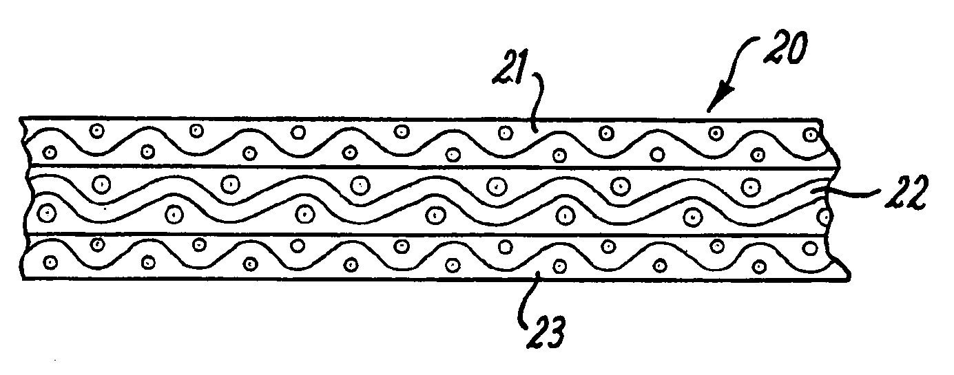
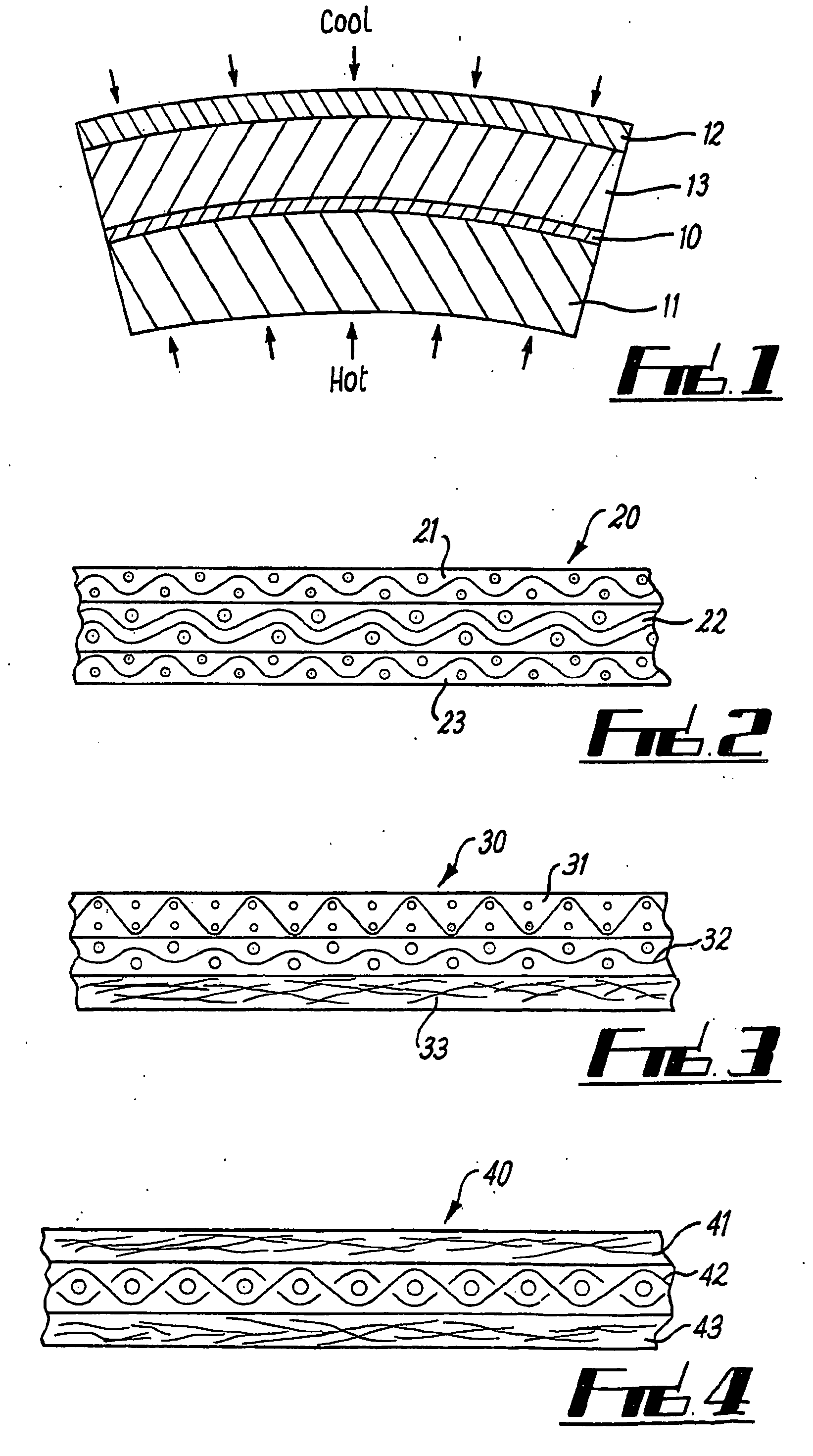
[0050]FIG. 1 is a diagrammatic sectional view of a roll in a dynamic condensation drying apparatus. This is a magnified view of part of the shell of the roll with superposed dryer and carrier belts, with the curvature exaggerated. The outer wall of the roll comprises a shell or steel surface 11, which is heated from within the roll. A paper web 10 is passed over the roll in contact with the heated shell 11, with a drier fabric 13 pressing if thereon. The dryer fabric also serves to transport the paper web 10, and to absorb moisture driven from the web 10. Belt 12 is exposed to lower temperatures on its outer-side. This may be by contact with ambient air, forced ventilation, or actively refrigerated air, or more preferably a reservoir of cooled water, which is sealed by belt 12. The heated surface of cylinder 11 is between the range 120° C.-180° C., whilst the belt 12 is maintained in the range 20° C.-90° C., that is below boiling point so that condensation can take place.

[0051] In ...


PUM

PropertyMeasurementUnit
Temperatureaaaaaaaaaa
Pore sizeaaaaaaaaaa
Diameteraaaaaaaaaa

Abstract

A fabric for use in dynamic condensation drying apparatus comprises a single fabric comprising at least a core layer (22) of relatively large structure and large void size, and a paper support layer (21) of relatively fine structure and pore size, and optionally a cylinder side layer (23) of intermediate structure and pore size. A range of alternatives are shown, including the use of fibrous batts, woven fabrics, perforated membranes, sintered layers, chain-link fabrics, and honeycomb layers, as well as unitary woven or sintered fabrics incorporating the layers in a single structure.

Description

CROSS-REFERENCE TO RELATED APPLICATIONS [0001] The present application is a U.S. National Stage of International Patent Application No. PCT / GB2003 / 004585 filed Oct. 24, 2003, and claims priority of Great Britain Patent Application No. 0224749.2 filed Oct. 24, 2002 and Great Britain Patent Application No. 0230211.5 filed Dec. 27, 2002.BACKGROUND OF THE INVENTION [0002] 1. Field of the Invention [0003] This invention relates to a fabric for use in a so-called dynamic condensation drying apparatus or other similar condensation drying processes in the manufacture of paper and board. [0004] 2. Discussion of Background Information [0005] A dynamic condensation drying apparatus involves the utilization of a heat source to generate water vapor within the wet web. This leads to an increase in vapor pressure and a thermodynamic drive for such moisture to leave the web. [0006] The moisture is then condensed by cooling, the water then being retained by the fabric to avoid re-wetting of the web....

Claims


Application Information

Patent Timeline
IPC IPC(8): B32B5/06B32B3/10D04H1/46B32B7/02B32B5/24D21F1/00
CPCD21F1/0036D21F1/0063Y10T428/24942Y10T428/24273Y10T428/24322D21F1/0072Y10T442/682Y10T442/3325Y10T442/3764Y10T442/3724Y10T428/249953Y10T442/3293
Inventor MORTON, ANTONY
Owner VOTH FABRICS PATENT GMBH
Why Eureka
Try Eureka