Coaxial cable connector and electronic device case
a technology of coaxial cable and electronic device case, which is applied in the direction of coupling device connection, electrical apparatus, connection, etc., can solve problems such as troublesome methods, and achieve the effects of preventing the rotation of coaxial cable, preventing falling out, and facilitating pulling ou
- Summary
- Abstract
- Description
- Claims
- Application Information
AI Technical Summary
Benefits of technology
Problems solved by technology
Method used
Image
Examples
first embodiment
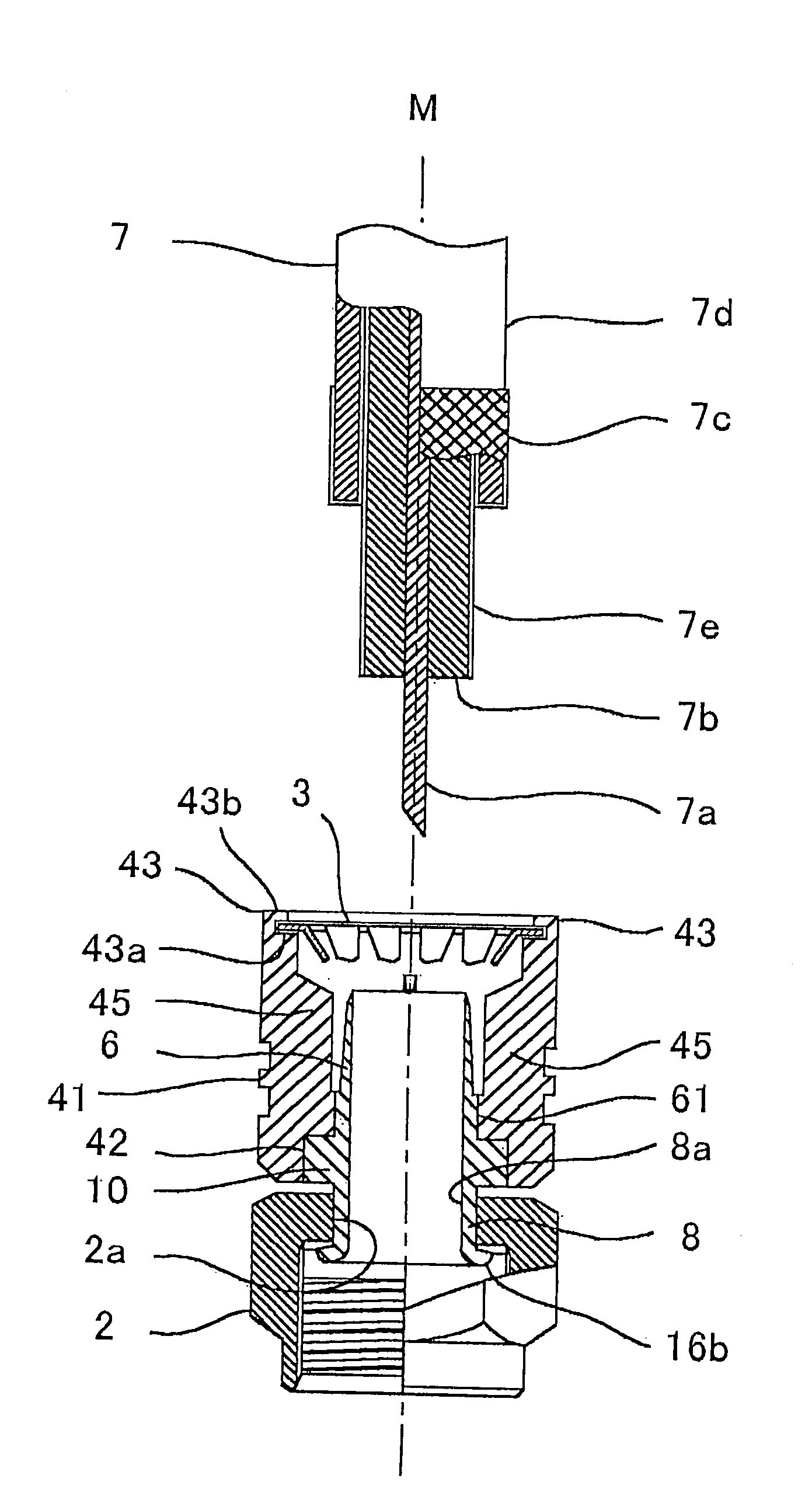
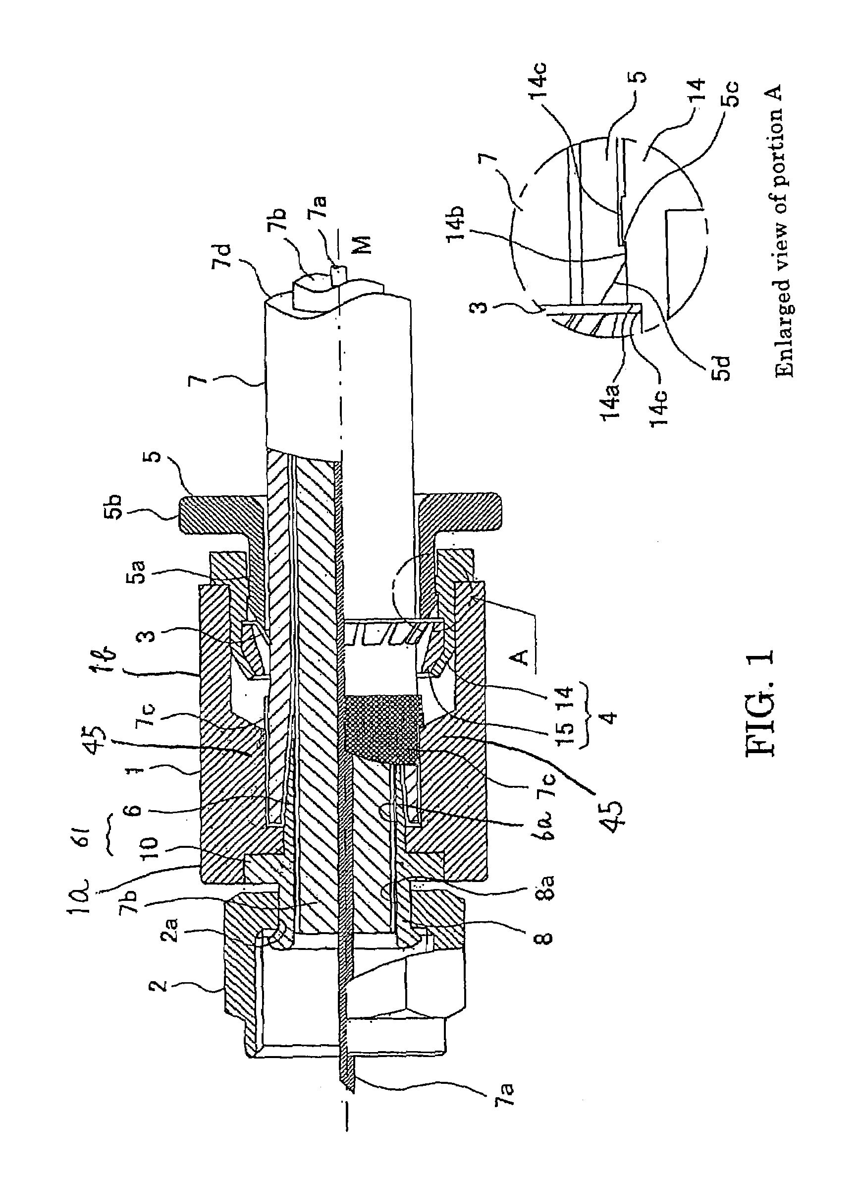
[0069]Hereinafter, embodiments of the present invention will be described in detail according to the drawings. FIG. 1 shows a coaxial cable connector (hereafter, referred to simply as a connector) related to the invention, and it is an explanatory view showing an important portion of the connector mounted in the coaxial cable, with a partly-enlarged view.
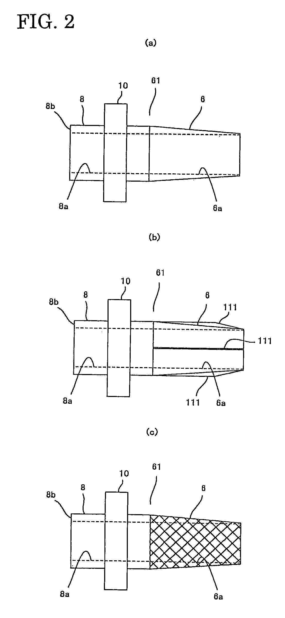
[0070]In FIG. 1, the reference numeral 1 indicates a main body of the cylindrical connector, including cable-attaching means, for covering a coaxial cable (hereafter, referred to simply as a cable) and the reference numeral 2 indicates a connecting means for connecting the cable to a connecting object such as a receptacle, which is a nut in this embodiment. The cable-attaching means includes a stopper 3 for preventing the inserted cable from falling out, an anchor 4 for fixing the stopper 3, a releaser 5 for releasing the lock function of the stopper 3, and a sleeve 61 having an inserting portion 6 to be inserted between an inner in...
second embodiment
[0102]The bolt 20 is integrally formed at the front of the ring-shaped joining portion 10. The bolt 20, the ring-shaped joining portion 10, and the inserting portion 6 constitute the sleeve 62. The reference numeral 21 denotes a main body of the connector in the
[0103]The bolt 20 includes a communicating hole 22 which communicates with the through hole 6a of the sleeve 6 within the connector main body 21, where the central conductor (not illustrated) of the connecting object is inserted on the central axis M. Within the connecting hole 22, a fitting metal 23 is provided for joining the central conductor 7a of the cable 7 inserted into the connector main body 21, with the central conductor (not illustrated) of the connector of the connecting object. The fitting metal 23 is arranged within a cylindrical supporter 24 made of resin and the cylindrical supporter 24 has apertures 24a through which the central conductor penetrates on the front and back surfaces thereof respectively.
[0104]Th...
fourth embodiment
[0121]As well illustrated in FIG. 12, the stopper 130 in this fourth embodiment has a fastening claw denoted as 130c on the fastening portion 130b which corresponds to the fastening portion 3b of the stopper 3. One or a plurality of the fastening claw(s) 130c is / are disposed and folded at the periphery of the fastening portion 130b so as to protrude toward the front of the connector.
[0122]As shown in FIG. 14(a) corresponding to this stopper 130, a fitting portion into which the fastening portion 130c is fitted is provided at the cable inserting portion 143 formed at the rear of the connector main body 41.
[0123]This cable inserting portion 143 has a stepped portion 143a in the interior of the opening portion similarly to the above embodiments. The periphery of the stepped portion 143a is configured so that the fastening portion 130b is internally abutted. In addition, when the fastening portion 130b of the stopper 130 is disposed so as to abut on the stepped portion 143a, the fitting...
PUM
 Abstract
Description
Claims
Application Information
 - R&D
- Intellectual Property
- Life Sciences
- Materials
- Tech Scout
- Unparalleled Data Quality
- Higher Quality Content
- 60% Fewer Hallucinations
Browse by: Latest US Patents, China's latest patents, Technical Efficacy Thesaurus, Application Domain, Technology Topic, Popular Technical Reports.
© 2025 PatSnap. All rights reserved.Legal|Privacy policy|Modern Slavery Act Transparency Statement|Sitemap|About US| Contact US: help@patsnap.com


