This helps you quickly interpret patents by identifying the three key elements:
Problems solved by technology
Method used
Benefits of technology
[0010]The fence faces can quickly and easily be replaced by way of the studs and the keyhole shaped slots. The adjustment mechanism and the cam provide the inventive fence with a lockdown that is mechanically simple and yet allows for acc
Problems solved by technology
None of these lockdowns provide the ability to accurately tune the position of the fence relative to the saw blade.
Further,
Method used
Image
Click on the blue label to locate the original text in one second.
Reading with bidirectional positioning of images and text.
Examples
Embodiment Construction
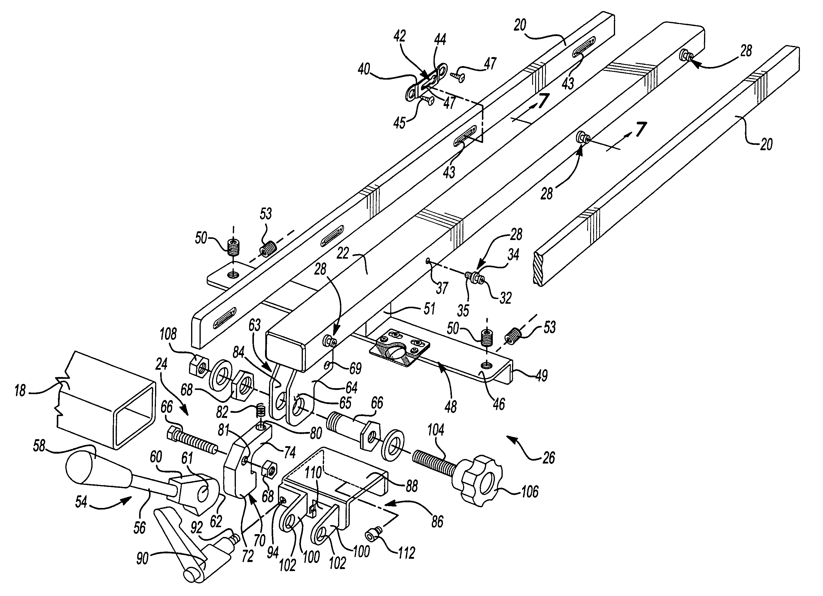
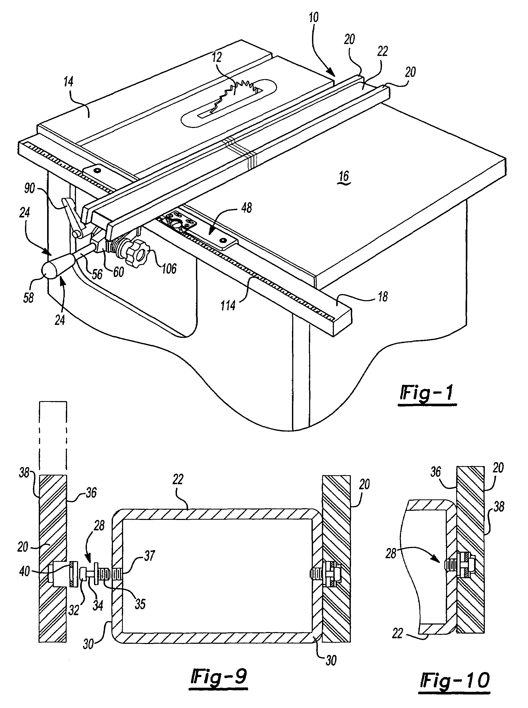
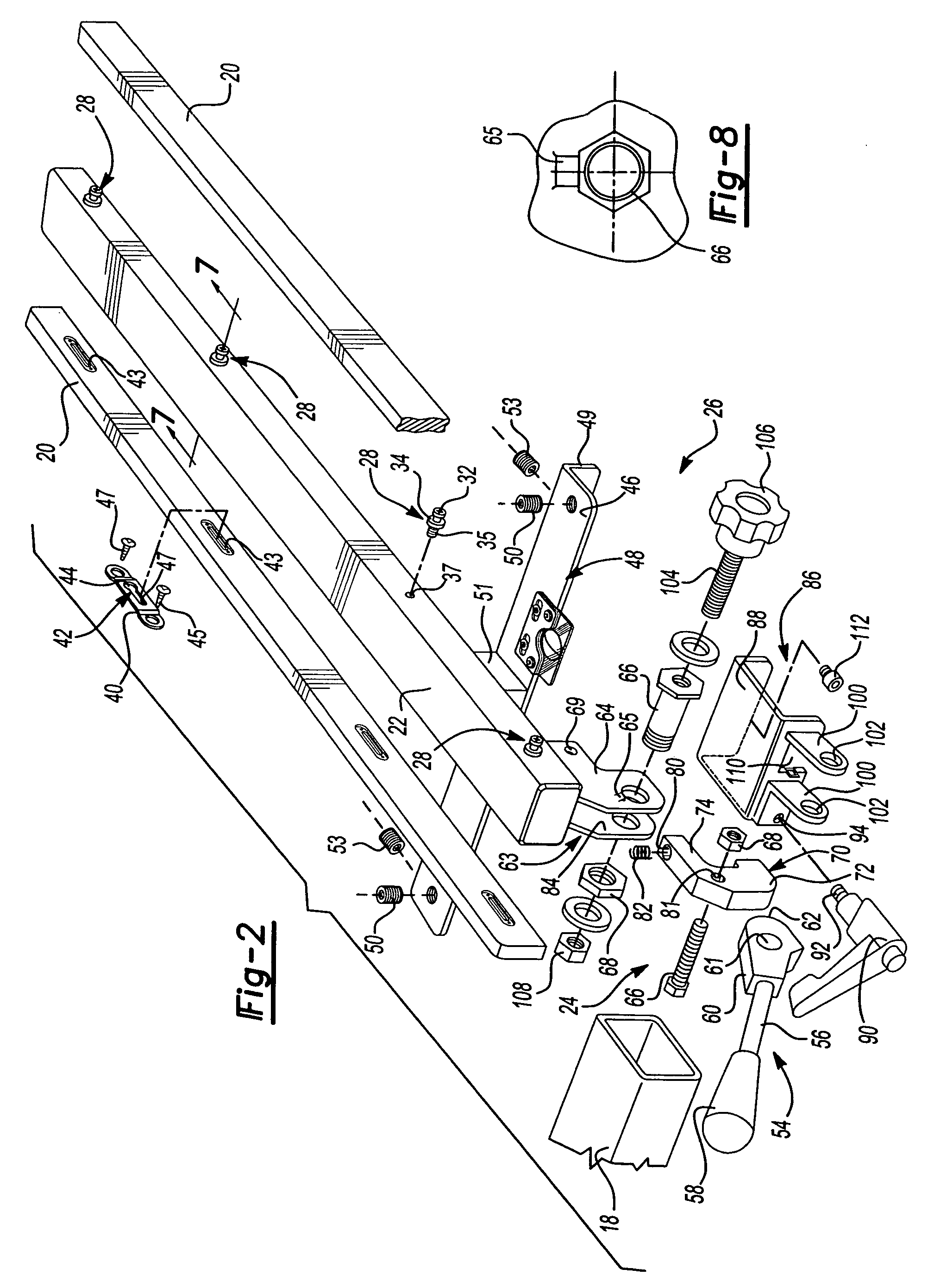
[0026]Referring to FIG. 1, a fence assembly is generally shown at 10. The fence 10 is used for guiding wood against a table mounted tool such as a saw blade 12 of a tablesaw 14. The fence 10 sits upon a work surface 16 of the tablesaw 14 and is aligned parallel to the saw blade 12. The tablesaw 14 includes a support tube 18 that runs perpendicular to the saw blade 14 as known in the art of tablesaws. Fence 10 is removably mounted to support tube 18. The fence 10 includes opposing fence faces 20 that extend upwardly and are removably attached to opposite sides of fence beam 22.
[0027]Referring to FIGS. 9 and 10, the preferred embodiment of the fence face 20 is illustrated. The fence faces 20 are removably affixed to opposing sides of the fence beam 22 by a plurality of studs 28 which project outwardly from each beam side 30 of the fence beam 22. Each stud includes a head 32 and a shaft 34. The radius of the head 32 is larger than that of the shaft 34. The shaft 34 extends outwardly fr...
PUM
Abstract
A fence for guiding a work surface past a saw blade supported by a table having a support tube running substantially perpendicular to the saw blade. The fence includes a rip fence having a plurality of studs disposed on opposing sides thereof. A pair of fence faces are positioned on opposing sides of the rip fence and have a plurality of slots for removably engaging the studs thereby securing the face fences to the rip fence. A rip fence head is affixed beneath the rip fence. A lockdown clasps the support tube with the rip fence head for securing the fence to the tablesaw. The lockdown includes an adjustment mechanism for stabilizing the fence to the support tube independently of the lockdown. The adjustment mechanism is adjustable relative to the lockdown so that the position of the fence on the support tube can be accurately adjusted by moving the fence relative to the lockdown mechanism.
Description
[0001]This application is a divisional application of application Ser. No. 10 / 657,289, filed Sep. 8, 2003, which is a divisional application of U.S. patent application, Ser. No. 10 / 076,173, filed Feb. 14, 2002 now U.S. Pat. No. 6,647,847, which claims the benefit of Provisional Application No. 60 / 269,115, filed Feb. 15, 2001.BACKGROUND OF THE INVENTION[0002]This invention relates to an improved fence for a table mounted tool, such as for example a tablesaw, shaper, oscillating spindle sander, band saw, router table, etc. More specifically, the subject invention relates to an improved attachment for securing the fence to a table mounted tool and an improved way of replacing the fence faces or attaching accessory tools. For simplicity and clarity, the present invention will be described with respect to a tablesaw, but it should be understood that it will work well with any table mounted tool.[0003]Fences have become standard equipment for use with most tablesaws to accurately guide a ...
Claims
Application Information
Patent Timeline
Application Date:The date an application was filed.
Publication Date:The date a patent or application was officially published.
First Publication Date:The earliest publication date of a patent with the same application number.
Issue Date:Publication date of the patent grant document.
PCT Entry Date:The Entry date of PCT National Phase.
Estimated Expiry Date:The statutory expiry date of a patent right according to the Patent Law, and it is the longest term of protection that the patent right can achieve without the termination of the patent right due to other reasons(Term extension factor has been taken into account ).
Invalid Date:Actual expiry date is based on effective date or publication date of legal transaction data of invalid patent.