Drawer locking apparatus of a cabinet

a locking apparatus and drawer technology, applied in the direction of building locks, construction, construction fastening devices, etc., can solve the problems of inconvenient and troublesome locking operation of drawers, high cost of manufacturing time and labor, and relatively high cost of materials of such structures, so as to facilitate assembly, easy and convenient locking, and the cost of materials of these components is low

Active Publication Date: 2007-09-04
E MAKE
View PDF5 Cites 15 Cited by
  • Summary
  • Abstract
  • Description
  • Claims
  • Application Information

AI Technical Summary

Benefits of technology

[0007]It is therefore a primary object of the present invention to provide a drawer locking apparatus of a cabinet. The drawing locking apparatus includes simpler components which can be more easily assembled. The cost for the materials of these components is lower. After the locking apparatus is locked, in the case that some other drawers are not locked, all the drawers can be easily and conveniently locked.

Problems solved by technology

However, it often takes place that after locking the drawers, a user finds that one or some of the drawers are not totally pushed in and are not locked.
This makes it inconvenient and troublesome to perform the locking operation for the drawers.
The cost for manufacturing time and labor and the cost for the material of such structure are relatively high.

Method used


Image

  • Drawer locking apparatus of a cabinet
  • Drawer locking apparatus of a cabinet
  • Drawer locking apparatus of a cabinet

Examples


second embodiment

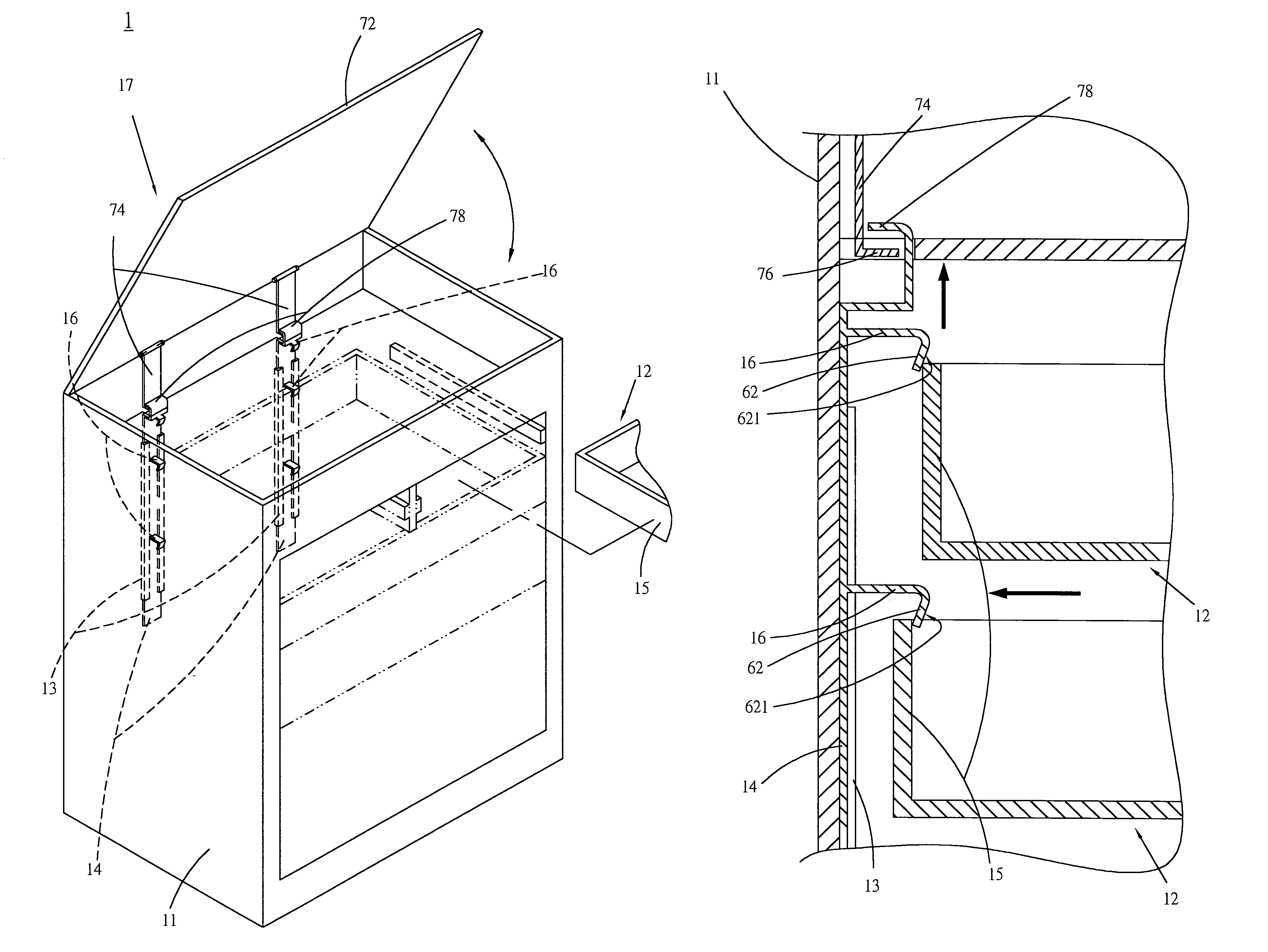
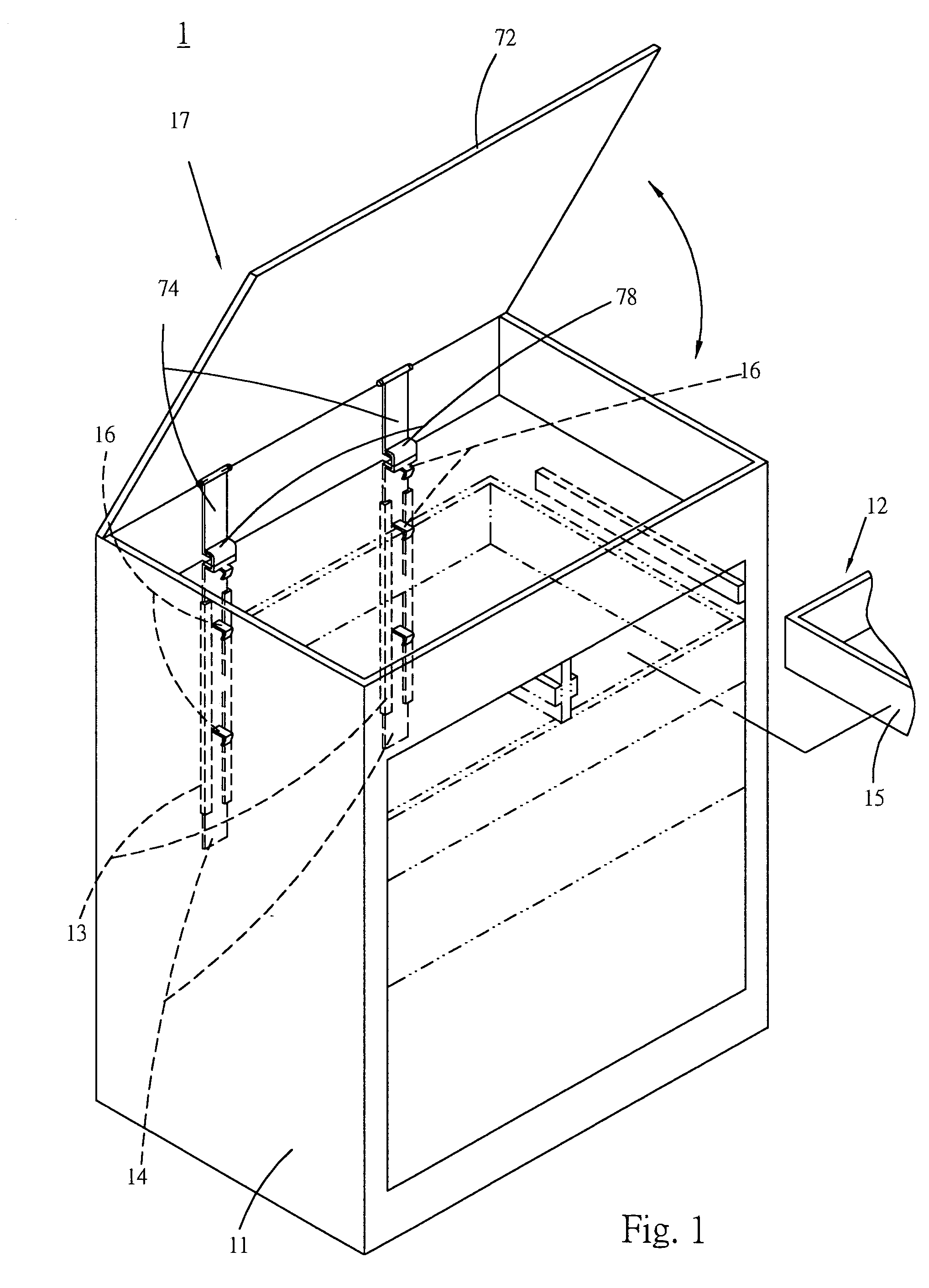
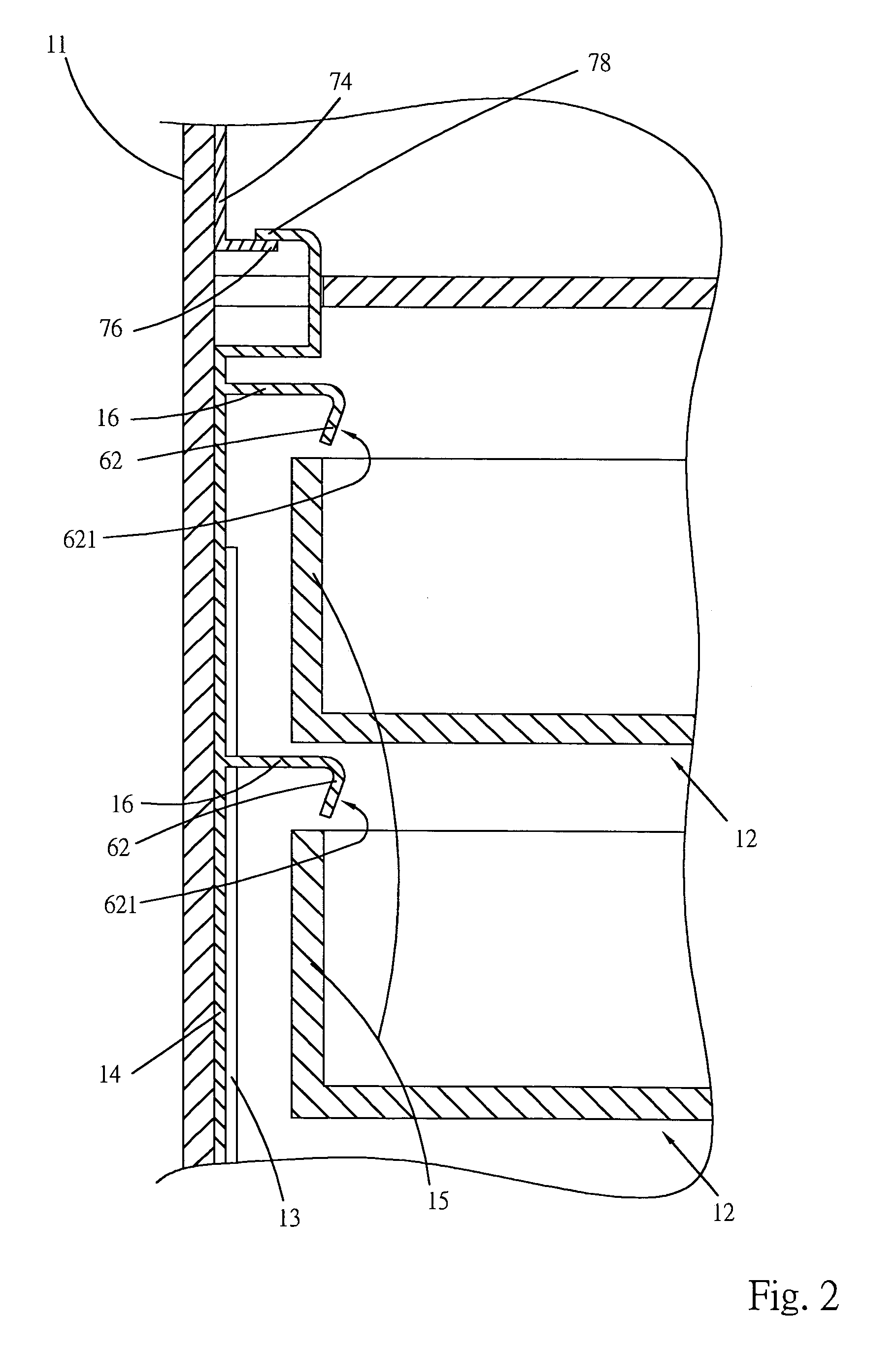
[0032]Referring to FIGS. 6 to 8 and FIG. 6A, the force application section 72 is a rod body with a certain length. The rod body passes through the transmission section 74. One end of the rod body is pivotally connected with the rear panel of the cabinet body 11 corresponding to rear side of the drawer 12. The other end of the rod body is pivotally connected with the cabinet body 11 corresponding to front side of the drawer 12 and exposed to outer side of the cabinet body 11. The other end of the rod body is equipped with a key-driven unit. The rod body has a bent section 721 for abutting against the transmission section 74. The two end points of the rod body and the contact point of the rod body in contact with the transmission section 74 are not collinear. By means of turning the key-driven unit, the transmission section 74 can be driven to drive the slide section 14 to slide between the first and second positions.

[0033]The transmission section 74 is formed with a polygonal hole 7...

third embodiment

[0034]FIGS. 9 and 10 show the present invention, in which the force application section 72 includes a resilient member 72′ and a cover board 72″. The resilient member 72′ can be a coiled spring disposed at the middle of the transmission section 74 for driving the same.

[0035]One side of the cover board 72″ is pivotally connected with one side of the panel of the cabinet body 11, on which the base seat 13 is mounted. The cover board 72″ is positioned on upper side of the cabinet body 11 to abut against upper end of the transmission section 74 or release the upper end of the transmission section 74. When the cover board 72″ is pivoted up and opened, the transmission section 74 is released from the abutting force of the cover board 72″. The resilient member 72′ pushes the transmission section 74 to move upward or the resilient member 72′ pushes the transmission section 74 to move upward and still abut against the cover board 72″, whereby the slide section 14 is positioned in the first p...


PUM


Abstract

A drawer locking apparatus of a cabinet, including a cabinet body, at least one drawer slidably disposed in the cabinet body, a base seat mounted in the cabinet body, a slide section slidably fitted in the base seat, an engaging section and a dogging device. One end of the engaging section is disposed on the slide section. The other end of the engaging section has a hook plate with a guide slope for hooking rear sideboard of the drawer. The dogging device serves to drive the slide section to slide between a first position and a second position.

Description

BACKGROUND OF THE INVENTION[0001]The present invention is related to a drawer locking apparatus, and more particularly to a drawer locking apparatus of a file cabinet or a tool cabinet.[0002]A conventional file or tool cabinet is a substantially rectangular case body with six faces. The case body is formed by several panels defining a space therebetween. Several drawers are horizontally disposed in the space layer by layer for placing documents or tools therein. In order to prevent the documents or tools from being stolen or prevent the drawers from dropping out due to shock or inclination of the ground, the file or tool cabinet is equipped with a locking device for locking the drawers.[0003]In order to lock the respective drawers at one time, a conventional device or such as U.S. Pat. No. 4,966,422 disclose a locking device including an up and down movable latch body disposed on the panels of the case body. Each drawer has a hook section corresponding to a latch hole or a latch sec...

Claims


Application Information

Patent Timeline
Patent Type & Authority Patents(United States)
IPC IPC(8): E05C7/06E05B65/462
CPCE05B65/462
Inventor CHENG, CHEN KUNG
Owner E MAKE
Why Eureka
Try Eureka