Recording-medium conveying device conveying a recording medium on a conveying belt charged with a positive charge and a negative charge alternately
a conveying device and recording medium technology, applied in the direction of thin material processing, printing, other printing apparatus, etc., can solve the problems of increasing the cost of the image-forming device as a whole, difficult color overlapping step,
- Summary
- Abstract
- Description
- Claims
- Application Information
AI Technical Summary
Benefits of technology
Problems solved by technology
Method used
Image
Examples
embodiments 1-4
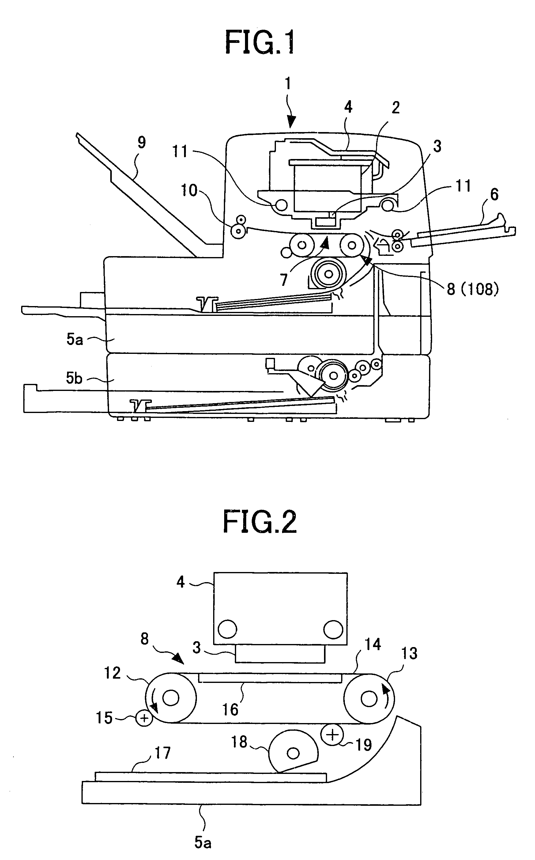
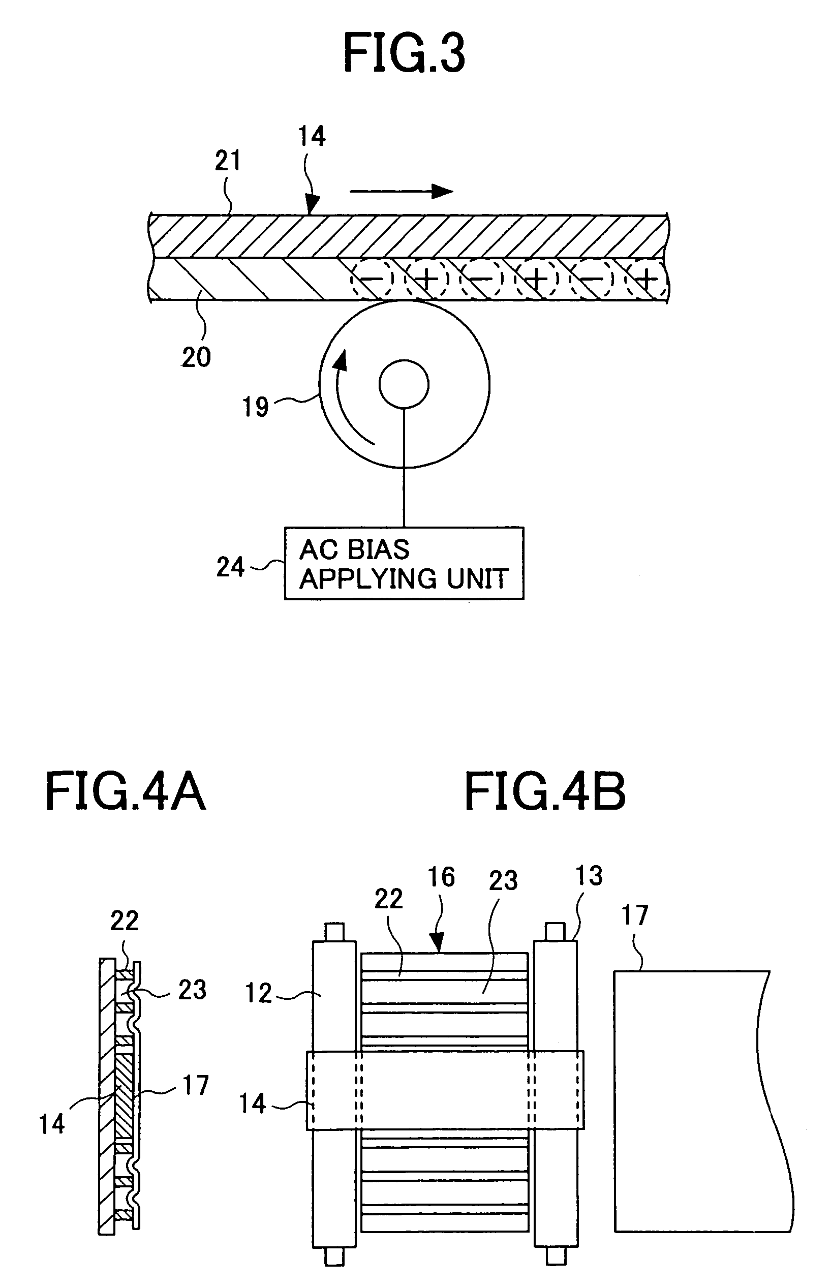
[0131]FIG. 1 is an illustration of a configuration of an inkjet printer according to a first embodiment of the present invention. As shown in FIG. 1, an inkjet printer 1 comprises four ink cartridges 2, four recording heads 3, a carriage 4, feeding trays 5a and 5b, a manual feeding tray 6, a recording-sheet conveying device 8, a delivery tray 9, and a delivery roller 10. The four ink cartridges 2 contain four inks of cyan C, magenta M, yellow Y, and black Bk, respectively. The four recording heads 3 have a plurality of nozzles, and are supplied with the inks from the four ink cartridges 2, respectively. The ink cartridges 2 and the recording heads 3 are mounted on the carriage 4. The feeding trays 5a and 5b contain recording sheets. The feeding trays 5a and 5b and the manual feeding tray 6 form a recording-medium feeding device. The recording-sheet conveying device 8 conveys a recording sheet from the feeding trays 5a, 5b, or the manual feeding tray 6 to a printing part (an image re...
embodiment 5
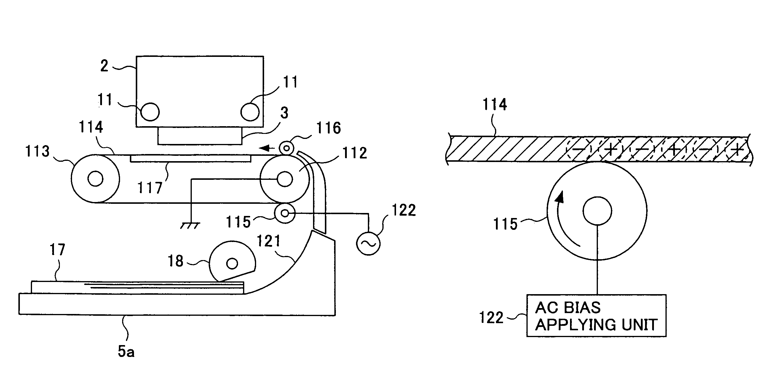
[0142]FIG. 13 is an illustration of a configuration of a recording-sheet conveying device according to a fifth embodiment of the present invention. As shown in FIG. 13, a recording-sheet conveying device 108 comprises a conveying belt 114, a belt charging roller (a belt charging unit) 115, a pressing roller 116, and a conveyance guide 117. The conveying belt 114 is wound around a driving roller 112 and a driven roller 113, and is capable of moving back and forth. The driving roller 112 is connected to a ground. A surface of the conveying belt 114 contacting the belt charging roller 115 is formed of an insulating layer. As shown in a sectional view of FIG. 14A and a top view of FIG. 14B, the conveying belt 114 is narrower than the recording sheet 17, and is wound around central parts of the driving roller 112 and the driven roller 113. The belt charging roller 115 is arranged opposite the driving roller 112 at a position upstream in a revolving direction of the driving roller 112, i....
embodiment 6
[0150]FIG. 17 is an illustration of a configuration of an inkjet printer according to a six embodiment of the present invention. As shown in FIG. 17, an inkjet printer 201 of a serial type comprises four ink cartridges 202, a recording head 203, a carriage 204, feeding trays 205a and 205b, a manual feeding tray 206, a recording-sheet conveying device 208, a delivery tray 209, and a delivery roller 210. The four ink cartridges 202 contain four inks of cyan C, magenta M, yellow Y, and black Bk, respectively. The recording head 203 has a plurality of nozzles, and are supplied with the inks from the four ink cartridges 202, respectively. The ink cartridges 202 and the recording head 203 are mounted on the, carriage 204. The feeding trays 205a and 205b contain recording sheets. The feeding trays 205a and 205b and the manual feeding tray 206 form a recording-medium feeding device. The recording-sheet conveying device 208 conveys a recording sheet from the feeding trays 205a, 205b, or the ...
PUM
 Abstract
Description
Claims
Application Information
 - R&D
- Intellectual Property
- Life Sciences
- Materials
- Tech Scout
- Unparalleled Data Quality
- Higher Quality Content
- 60% Fewer Hallucinations
Browse by: Latest US Patents, China's latest patents, Technical Efficacy Thesaurus, Application Domain, Technology Topic, Popular Technical Reports.
© 2025 PatSnap. All rights reserved.Legal|Privacy policy|Modern Slavery Act Transparency Statement|Sitemap|About US| Contact US: help@patsnap.com


