
Meter register having an encoder

a technology of encoder and meter register, which is applied in the direction of converting sensor output, liquid/fluent solid measurement, instruments, etc., can solve the problems of time-consuming, laborious, and expensive process of individually and visually reading water meters, and the use of reed switches and magnets on wheels is rather expensive, and the expense of gears is 312

Active Publication Date: 2007-09-11
ARAD MEASURING TECH
View PDF139 Cites 32 Cited by
  • Summary
  • Abstract
  • Description
  • Claims
  • Application Information

AI Technical Summary

Benefits of technology

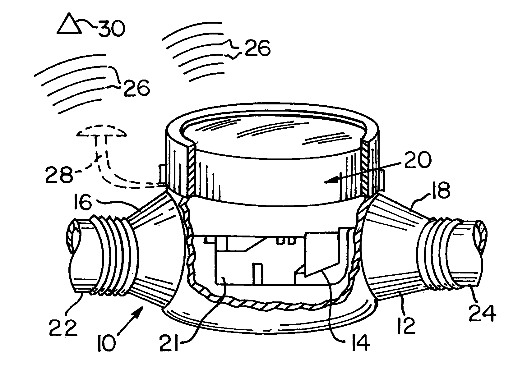
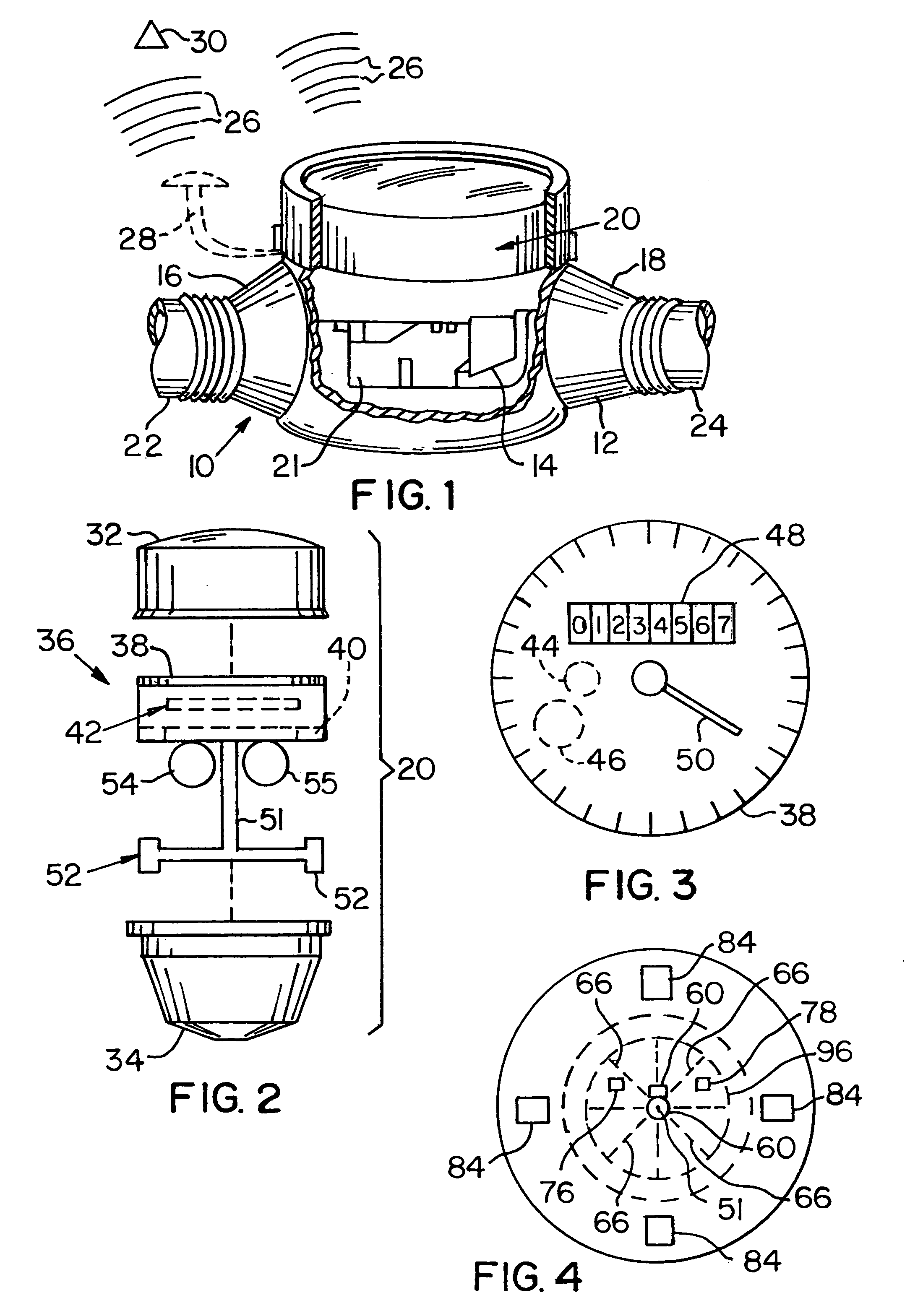
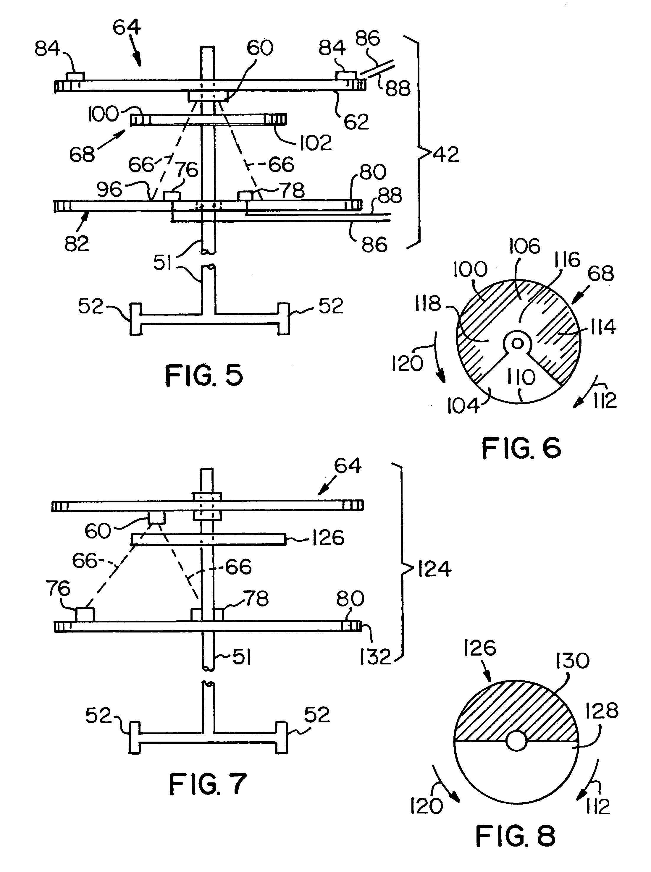
"The invention is about a meter register for measuring water usage. It includes a register body with a rotating shaft and a drive magnet attached to it. There is also an energy passing member that interacts with the shaft and has two surfaces. The first surface has a high percentage of energy transmission, while the second surface has a low percentage of energy transmission. The meter register also includes a device or emitter that emits energy in a specific wavelength range, and a pair of detectors that generate signals when energy passes through the register. These signals are used to measure the flow volume of water through the meter. The invention also includes a mechanical odometer that displays the amount of water used and a stepper motor that rotates the wheels of the odometer to show the amount of water used. The invention allows for more accurate and efficient water usage monitoring."

Problems solved by technology

This procedure of individually and visually reading water meters is time consuming, labor intensive, and expensive.
Although the meter register of WO 02 / 073735 is acceptable, there are limitations.
More particularly, the use of reed switches and magnets on a wheel are rather expensive and, due to their mechanical nature, can fail in the field.
A limitation of the encoder of application Ser. No. 10 / 864,312 is the expense of the gears.

Method used


Image

  • Meter register having an encoder
  • Meter register having an encoder
  • Meter register having an encoder

Examples


Embodiment Construction

[0033]In the following discussion of the non-limiting embodiments of the invention, spatial or directional terms, such as “inner”, “outer”, “left”, “right”, “up”, “down”, “horizontal”, “vertical”, and the like, relate to the invention as it is shown in the drawing figures. However, it is to be understood that the invention can assume various alternative orientations and, accordingly, such terms are not to be considered as limiting. Further, all numbers expressing dimensions, physical characteristics, and so forth, used in the specification and claims are to be understood as being modified in all instances by the term “about”. Accordingly, unless indicated to the contrary, the numerical values set forth in the following specification and claims can vary depending upon the desired properties sought to be obtained by the practice of the invention. At the very least, and not as an attempt to limit the application of the doctrine of equivalents to the scope of the claims, each numerical ...


PUM


Abstract

A water meter register has a shaft for rotating an energy passing wheel having a high transmission portion and a low transmission portion. Energy rays are directed toward one side of the wheel toward a pair of detectors mounted on the other side of the wheel. Each of the detectors generates a first signal when energy passing through the first wheel portion is incident thereon and a second signal when the energy from the devices is incident on the second wheel portion to determine water volume flow rate. In another embodiment, an electronic device acts on the signals from the detectors to provide an adjusted signal that is a more accurate measure of flow rate. In another embodiment, the register includes a plurality of wheels to display measured volume flow, and a stepper motor mount within the wheels to rotate the wheels to present a readable measured volume flow rate.

Description

CROSS REFERENCE TO RELATED APPLICATIONS[0001]This application claims the benefit of Provisional Application Ser. No. 60 / 612,339, filed Sep. 23, 2004, for a “Meter Register Having An Encoder” and of Provisional Application Ser. No. 60 / 674,423, filed Apr. 25, 2005, for a “Meter Register Having An Encoder”. Provisional Application Ser. Nos. 60 / 612,339 and 60 / 674,423 are hereby incorporated by reference in their entirety.[0002]The non-limiting embodiments of the present invention relate to the subject matter of U.S. patent application Ser. No. 10 / 864,312, filed Jun. 9, 2004, in the name of Dan Winter for “Meter Register Having An Encoder For Measuring Material Flow And An Algorithm To Selectively Block Signal Transmission” (hereinafter also referred to as “application Ser. No. 10 / 864,312”), and U.S. patent application Ser. No. 10 / 864,308, filed Jun. 9, 2004, in the names of Ronald Koch and Dan Winter for “Meter Register and Remote Meter Reader Utilizing A Stepper Motor” (hereinafter als...

Claims


Application Information

Patent Timeline
Patent Type & Authority Patents(United States)
IPC IPC(8): G01F1/05
CPCG01D5/3473G01K17/12G01F1/07
Inventor WINTER, DAN
Owner ARAD MEASURING TECH
Learn More