
Evaporative emissions control system including a charcoal canister for small internal combustion engines

a technology of evaporative emissions control and internal combustion engine, which is applied in the direction of combustion air/fuel air treatment, machines/engines, transportation and packaging, etc., can solve the problem of fuel vapor trapped in the charcoal canister, and achieve the effect of facilitating the collection and trapping of fuel vapors

Inactive Publication Date: 2007-09-11
TECUMSEH PROD CO +1
View PDF63 Cites 44 Cited by
  • Summary
  • Abstract
  • Description
  • Claims
  • Application Information

AI Technical Summary

Benefits of technology

"The present invention provides an evaporative emissions control system for small internal combustion engines. The system includes a fuel vapor control device, such as a charcoal canister, that is connected to the engine's fuel system and the air space above it. The charcoal canister contains charcoal media that trap fuel vapors when the engine is not running. When the engine is running, fuel vapors are purged from the canister and consumed by the engine. The system is automatic and requires no operator action. It prevents fuel vapors from escaping the engine and reduces emissions. The invention also includes a fuel tank cap with charcoal media to trap fuel vapors, and a fuel vapor control device integrated with the carburetor and fuel tank."

Problems solved by technology

Additionally, the fuel tank cap is in fluid communication with the carburetor fuel bowl such that that fuel vapors from the carburetor fuel bowl migrate to, and are trapped within, the charcoal media of the fuel tank cap.
When the engine is not running, vapors from the fuel tank are trapped within the charcoal canister.

Method used


Image

  • Evaporative emissions control system including a charcoal canister for small internal combustion engines
  • Evaporative emissions control system including a charcoal canister for small internal combustion engines
  • Evaporative emissions control system including a charcoal canister for small internal combustion engines

Examples


Embodiment Construction

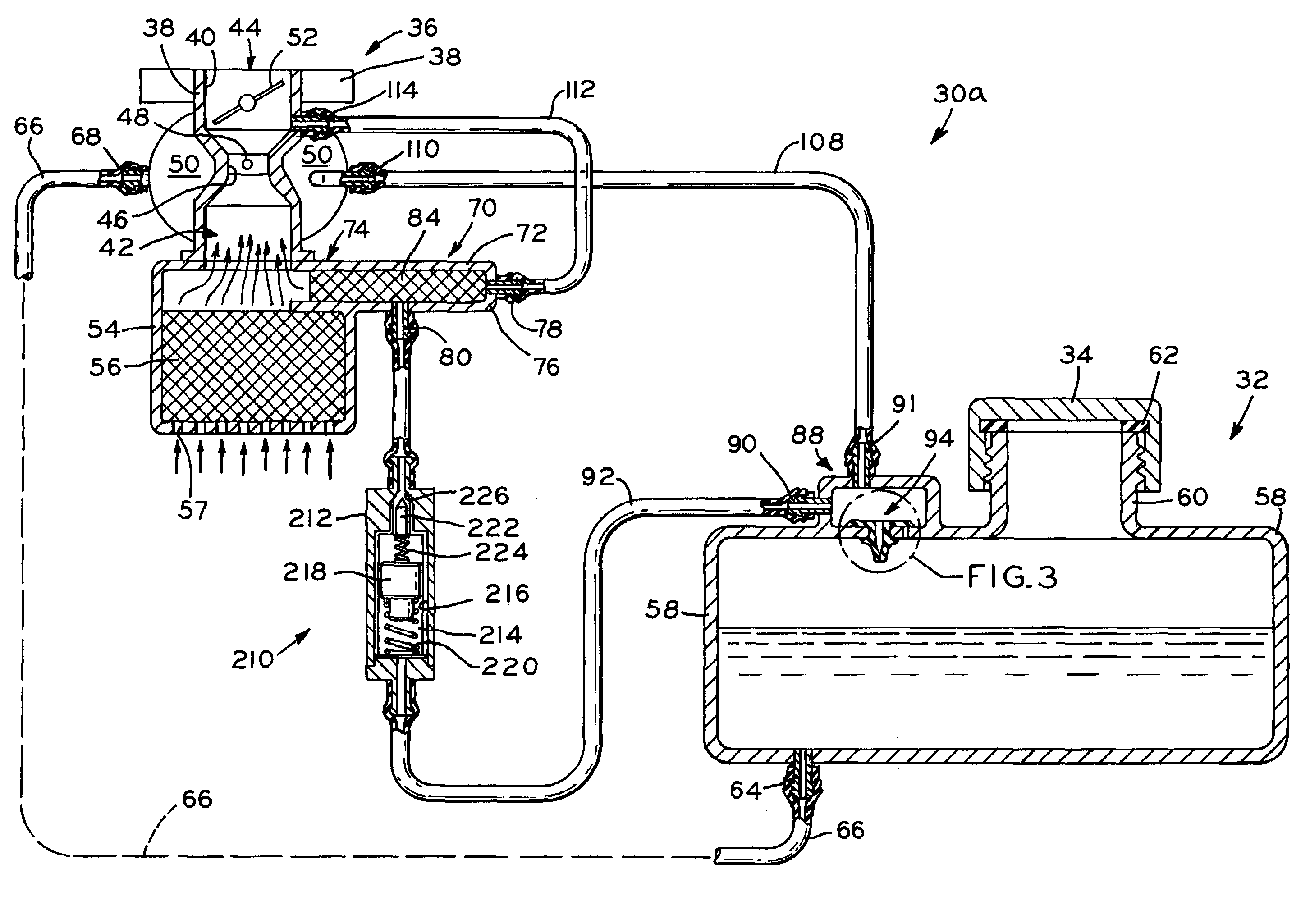
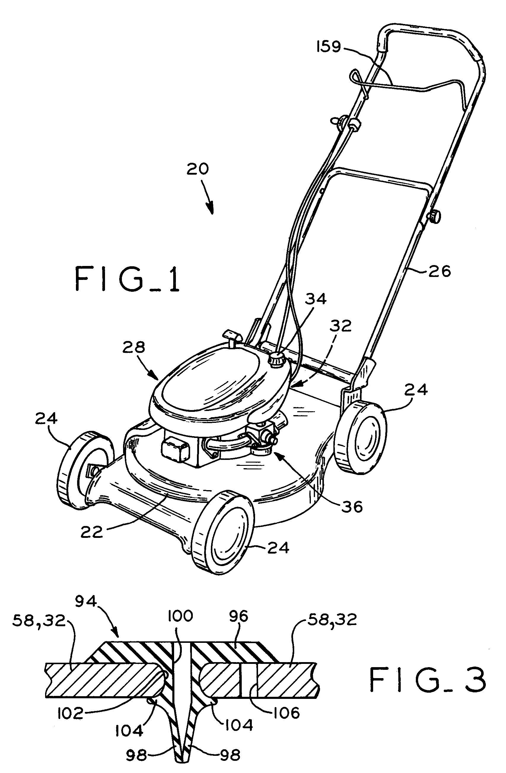
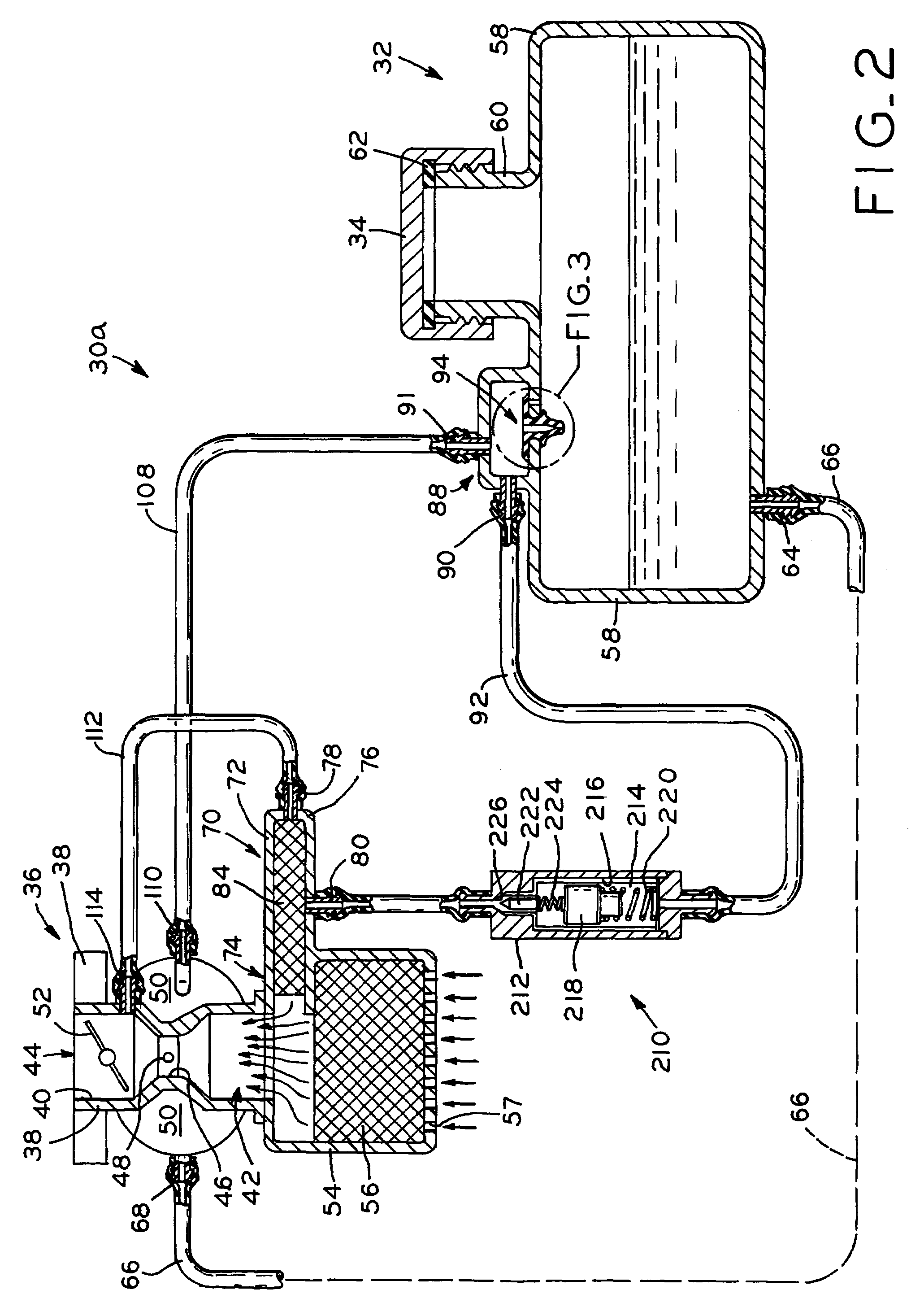
[0029]Referring first to FIG. 1, lawnmower 20 is shown as an example of an implement with which a small internal combustion engine may be used, the engine including an evaporative emissions control system of the present invention. Lawnmower 20 generally includes deck 22 having wheels 24, and a user-operable handle 26 extending upwardly from deck 22. A small internal combustion engine 28 is mounted to deck 22. Engine 28 is shown herein as a vertical crankshaft engine which drives a cutting blade (not shown) disposed beneath deck 22. However, the evaporative emissions control systems of the present invention are equally applicable to horizontal crankshaft engines, as well as engines having one, two, or more cylinders of the type commonly used with a variety of different types of implements, including lawnmowers, lawn and garden tractors, snow throwers, compressors, generators, and the like. Engine 28 includes fuel tank 32 storing liquid fuel, with fuel tank 32 closed by fuel tank cap ...


PUM


Abstract

An evaporative emissions control system for small internal combustion engines, including a charcoal canister which is in fluid communication with the air space above the liquid fuel within the carburetor of the engine and the air space above the liquid fuel within the fuel tank of the engine. The charcoal canister contains charcoal media, and when the engine is not running, fuel vapors from the carburetor and the fuel tank migrate to, and are trapped within, the charcoal media of the charcoal canister. The charcoal canister may comprise a separate component, or may be integrally formed with an engine component such as the air cleaner, the carburetor, or the body of the fuel tank, for example. During running of the engine, vacuum within the carburetor induces a flow of atmospheric air through the charcoal canister to purge the collected fuel vapors from the charcoal media, and the fuel vapors pass into the engine for consumption. In another embodiment, an evaporative emissions control system including a charcoal canister is provided for an engine which includes a fuel injection system.

Description

CROSS REFERENCE TO RELATED APPLICATIONS[0001]This application claims the benefit under 35 U.S.C. § 119(e) of U.S. Provisional Patent Application Ser. No. 60 / 540,994, entitled EVAPORATIVE EMISSIONS CONTROL SYSTEM INCLUDING A CHARCOAL CANISTER FOR SMALL INTERNAL COMBUSTION ENGINES, filed on Feb. 2, 2004, as well as U.S. Provisional Patent Application Ser. No. 60 / 559,505, entitled EVAPORATIVE EMISSIONS CONTROL SYSTEM INCLUDING A CHARCOAL CANISTER FOR SMALL INTERNAL COMBUSTION ENGINES, filed on Apr. 5, 2004.BACKGROUND OF THE INVENTION[0002]1. Field of the Invention[0003]The present invention relates to small internal combustion engines of the type used with lawnmowers, lawn tractors, other utility implements, and in sport vehicles, for example. In particular, the present invention relates to an evaporative emissions control system for such engines.[0004]2. Description of the Related Art[0005]Small internal combustion engines of the type used with lawnmowers, lawn tractors, other small u...

Claims


Application Information

Patent Timeline
Patent Type & Authority Patents(United States)
IPC IPC(8): F02M33/02B60K15/035F02B63/02F02M25/08F02M35/10
CPCF02M35/10222B60K15/03504F02M25/08F02M25/089F02M35/10019F02M35/1017F02M35/10196B60K2015/03557F02B63/02F02M25/0854F02M35/02
Inventor DONAHUE, RONALD J.CARPENTER, TODD L.KIRK, J. DAVIDHINTZ, GREGORY C.
Owner TECUMSEH PROD CO
Learn More