Railroad yard switch machine

a technology for switch machines and rail roads, applied in rail signalling, point operation from vehicles, transportation and packaging, etc., can solve problems such as frequent maintenance and repair, unnecessary increase in repair frequency and maintenance costs, and switch machines using damaged gears

Inactive Publication Date: 2007-09-11
SCHEER JERRY L
View PDF12 Cites 11 Cited by
  • Summary
  • Abstract
  • Description
  • Claims
  • Application Information

AI Technical Summary

Problems solved by technology

One problem with prior art switch machines is the large number of parts, and especially moving parts, thereby requiring frequent maintenance and repair.
In addition, typical switch machines utilize gears which can be damaged by vibration of the switch points as railroad cars roll through the switch.
These two such relays needlessly increase repair frequency and maintenance costs.
A further problem with conventional switch machines, whether powered or manual, resides in the back injuries sustained during manual operation of such switches.
The strain placed on the lower back of a railroad employee while attempting to operate the switch is substantial, and leads to frequent injuries and disabilities.

Method used


Image

  • Railroad yard switch machine
  • Railroad yard switch machine
  • Railroad yard switch machine

Examples


Embodiment Construction

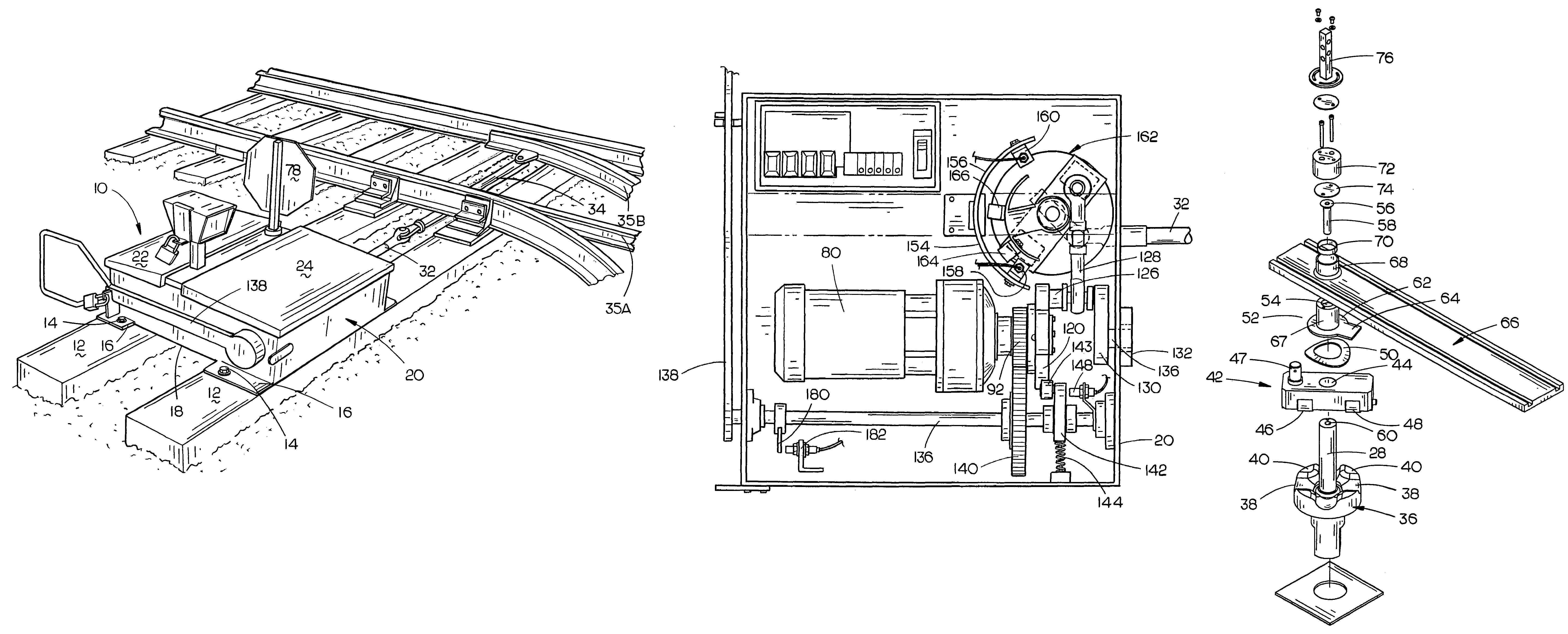
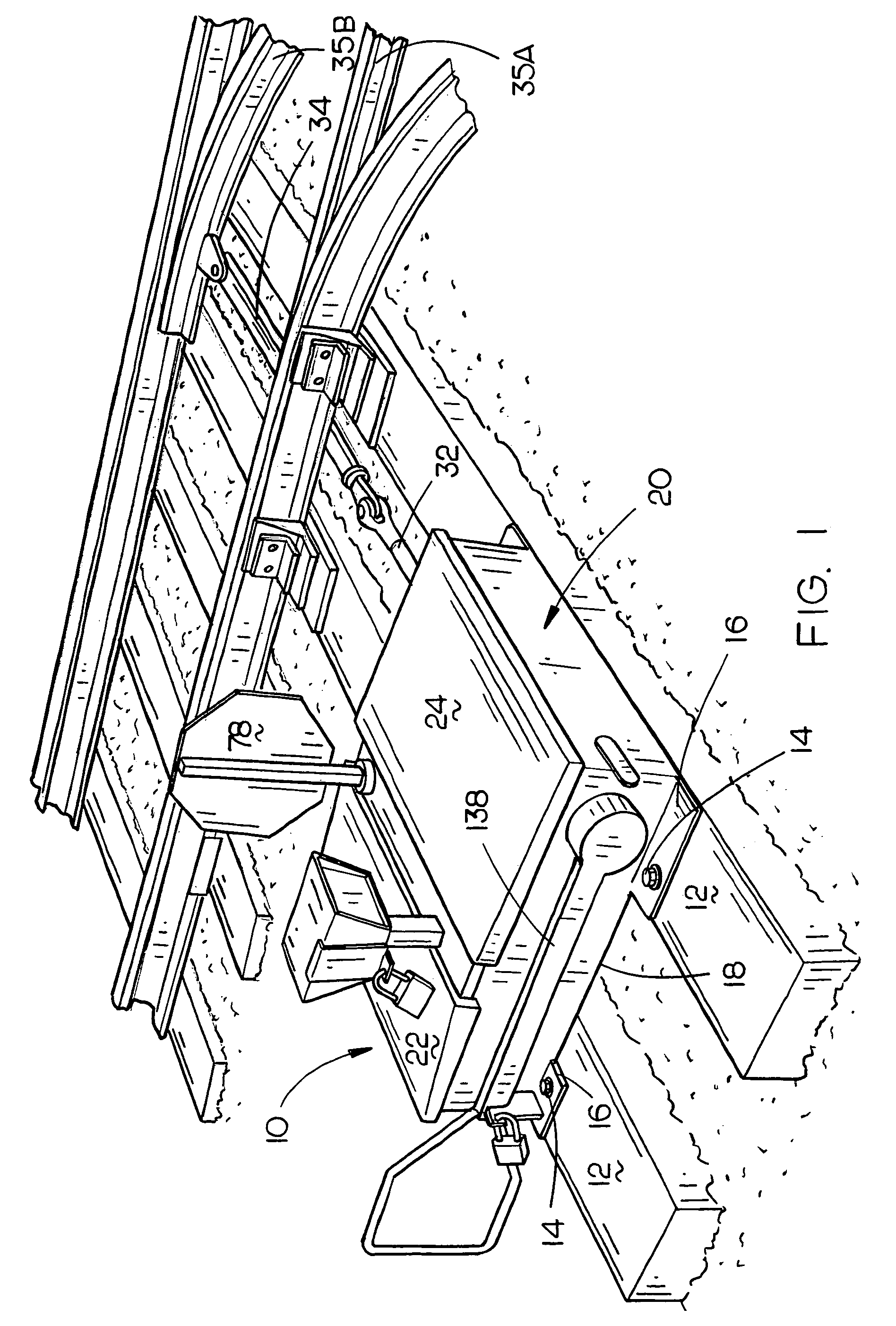
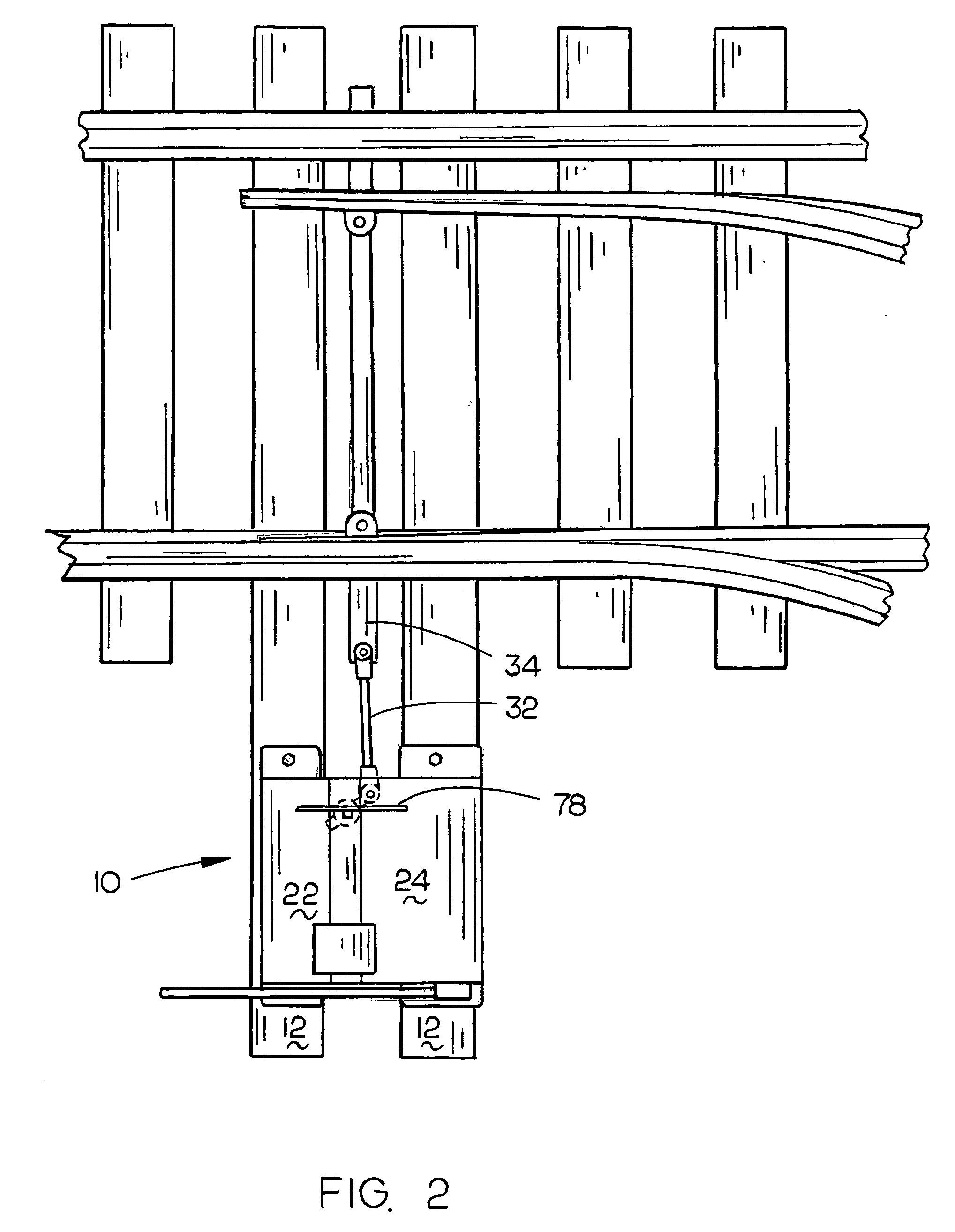
[0027]The numeral 10 refers generally to the switch machine of the present invention mounted on switch ties 12 using track spikes, drive screws or bolts 14 driven through holes in the tie mounting plates 16 which are secured to and extend from the base plate or bottom wall 18 of housing 20 which has covers or lids 22 and 24 enclosing the open upper end thereof. Base plate 18 is provided with an opening 26 formed therein through which extends a vertically disposed and rotatable shaft 28.

[0028]The lower end of shaft 28 has an internally threaded bore 29 which extends horizontally therethrough and which threadably adjustably receives the threaded end of a crank eye 30 which has one end of connecting rod 32 secured thereto by means of a pivot bolt 33 (FIG. 11). The other of connecting rod 32 is pivotally connected to the throw rod 34 extending from the switch points 35A and 35B. Shaft 28 is provided with a wave plate 36 having an upper surface which is provided with alternating grooves ...


PUM


Abstract

A railroad switch machine which is normally operated by an electric motor but which may be manually operated without causing rotation of the power shaft of the electric motor to enable the switch machine to move the switch points without having to overcome the brake resistance applied to the power shaft by the brake and gearbox thereof.

Description

BACKGROUND OF THE INVENTION[0001]1. Field of the Invention[0002]The present invention relates generally to railroad yard switch machines, and more particularly to an improved switch machine which may be electrically operated or manually operated, provides run-through capability, and has fewer moving parts than existing switch machines.[0003]2. Description of the Related Art[0004]Machines using hydraulic, pneumatic, or electrical energy to move railroad switch points to remotely or locally change the route of trains have been used for many years. These devices have been very useful for allowing remote operators to control the movement of trains on main lines and side tracks and also for distribution of railroad cars in railroad switch yards.[0005]Within recent years, the use of powered railroad switch movement devices (switch machines) has increased in railroad switch yards as a means of preventing debilitating strains and back injuries to personnel which sometimes results from use o...

Claims


Application Information

Patent Timeline
Patent Type & Authority Patents(United States)
IPC IPC(8): B61L5/00
CPCB61L5/02B61L5/065
Inventor SCHEER, JERRY L.
Owner SCHEER JERRY L
Why Eureka
Try Eureka