Two site infusion apparatus

a technology of infusion apparatus and pulsatile fluid, which is applied in the direction of mechanical apparatus, transportation and packaging, functional valve types, etc., can solve the problems of uneven delivery of medication, back pressure may reduce or stop the flow of medication on the side, and unfavorable patient safety

Inactive Publication Date: 2007-09-11
STRYKER CORP
View PDF10 Cites 55 Cited by
  • Summary
  • Abstract
  • Description
  • Claims
  • Application Information

AI Technical Summary

Problems solved by technology

Furthermore, if the flow of medication on one side of the “Y” has a greater restriction than on the other side, back pressure may reduce or stop the flow of medication on that side.
This is undesirable.
This solution presents several problems, namely, there is a time delay added by the opening and closing of the check valve and differences in manufacturing tolerances contributing to the delay may also lead to uneven delivery of the medication.
Furthermore, most check valves restrict flow when open, and unequal or uncontrollable variations in this restriction would lead to unequal flow.
This solution presents several problems.
First, the maximum pressure reached to provide the necessary flow split accuracy can be very high.
This can interfere with other pump features such as an occlusion alarm, and can cause sealing difficulties.
Second, if the pump has a user selectable flow rate, the size of the glass orifice must be fixed to work with the lowest possible flow rate.
This aggravates the maximum pressure problem should the pump be used at its highest flow rates.

Method used


Image

  • Two site infusion apparatus
  • Two site infusion apparatus
  • Two site infusion apparatus

Examples


Embodiment Construction

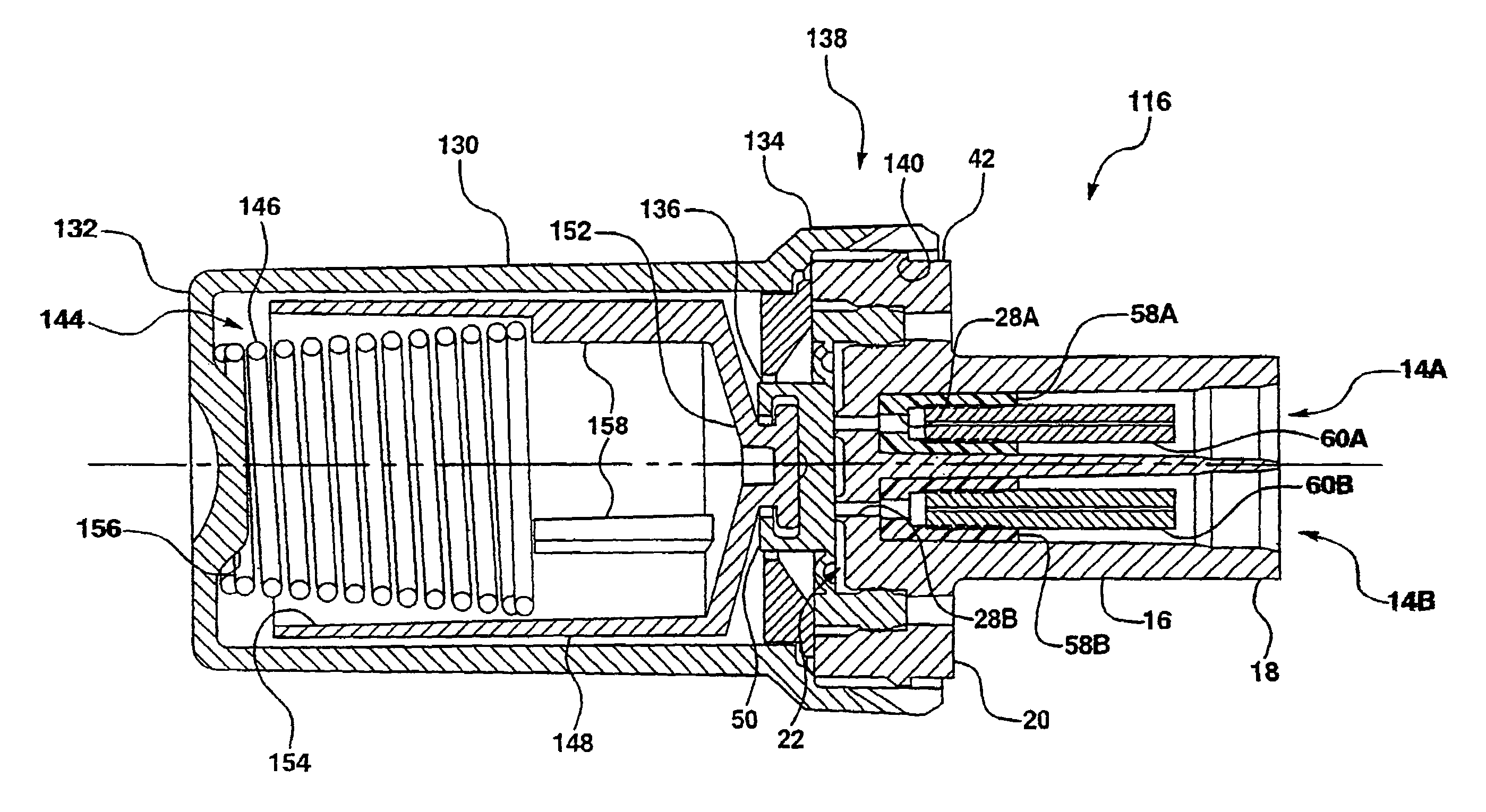
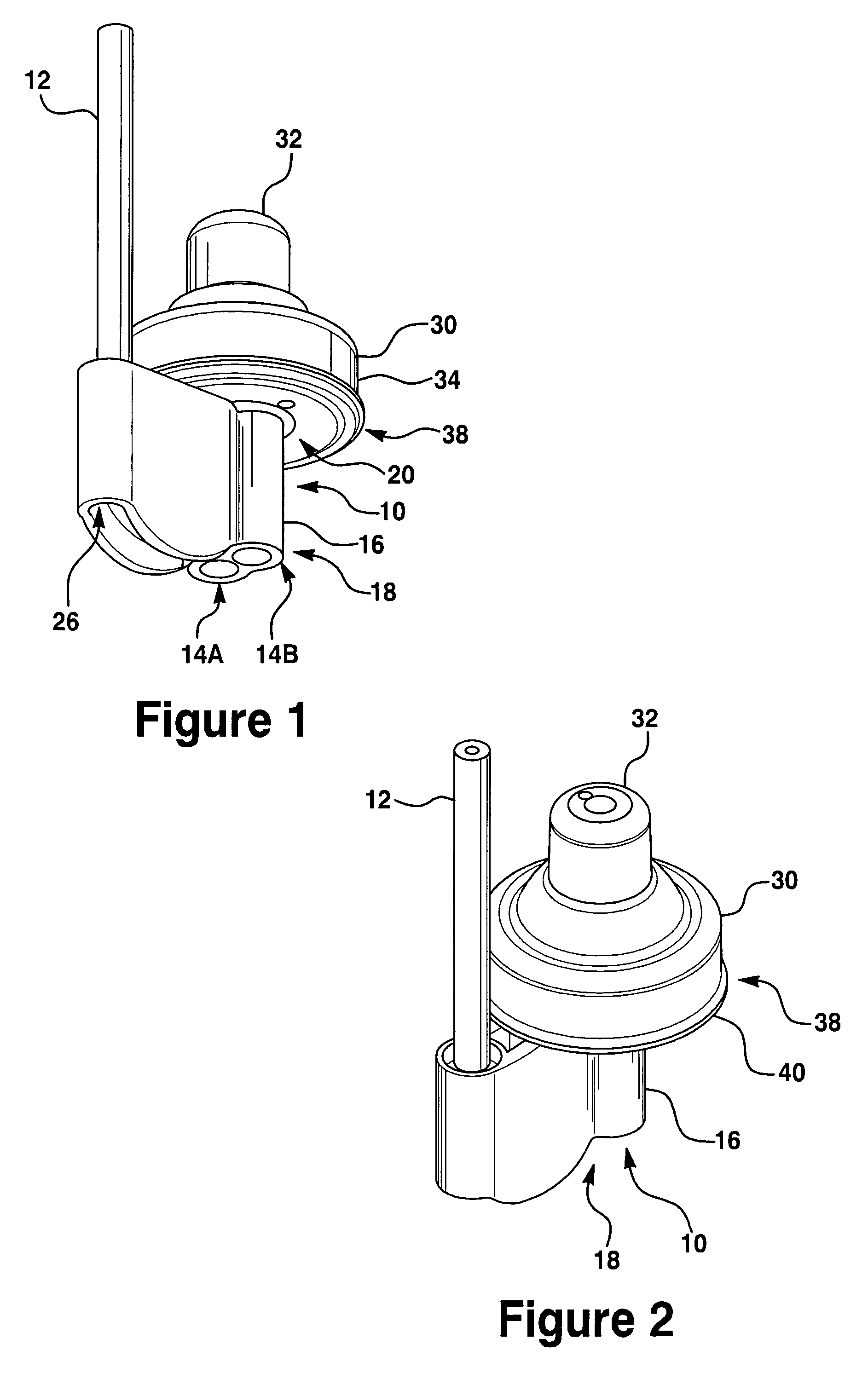
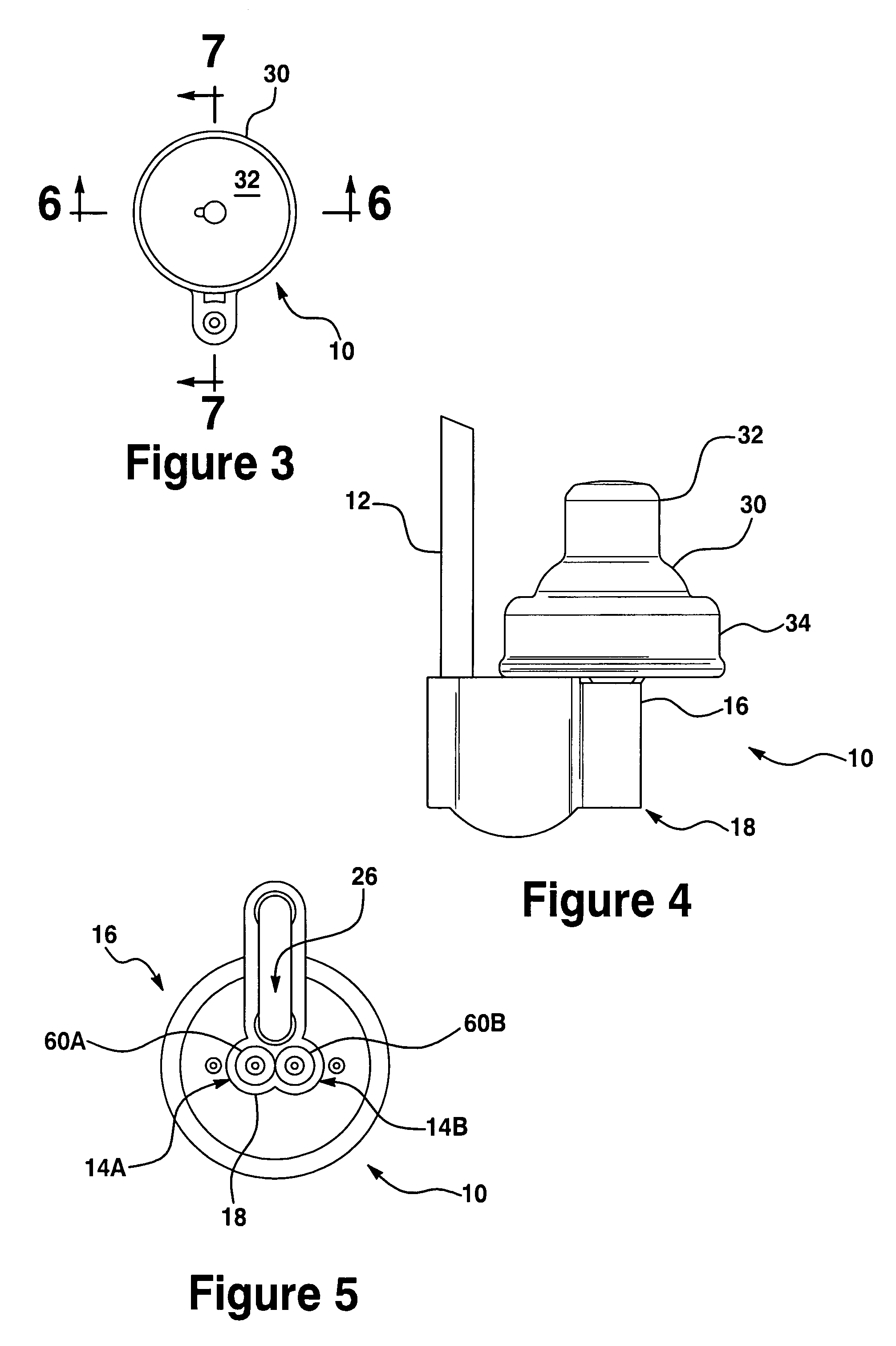
[0031]With reference to the drawings and in operation, the present invention provides an apparatus 10 for use in delivering pain medication to separate locations from a single pulsatile source of medication (or two site infusion apparatus). In one embodiment, the source of medication is a medication delivery system which includes a positive displacement pump (not shown). For example, the medication delivery system could include an electrical motor. The system is designed to deliver through a tube or inlet tube 12 a preset amount of medication every revolution or cycle of the motor. The rate at which medication is delivered may be set by varying the time between cycles of the motor.

[0032]In one aspect of the present invention, the two site infusion apparatus 10 is coupled to the output tube 12. The two site infusion apparatus 10, as discussed below, splits the medication delivered from the delivery system and delivers the medicine through first and second outlet orifices 14A, 14B.

[00...


PUM


Abstract

An apparatus for use in delivering pain medication to separate locations from a single source of pressurized medication includes a valve housing, a cap, and a flexible diaphragm. The valve housing includes a first end and a second end and an inlet passage. The first end includes first and second outlet orifices. The cap has a closed end and an open end and is removably coupled to the valve housing at the open end. The flexible diaphragm is coupled between the cap and the valve housing and is movable from a closed position to an open position. The flexible diaphragm seals a pressure chamber from the first and second outlet orifices when in the closed position and opens the first and second outlet orifices to the pressure chamber when in the open position.

Description

[0001]This application claims priority to U.S. Provisional Application Ser. No. 60 / 451,161, filed Feb. 28, 2003, and is a continuation of U.S. patent application Ser. No. 10 / 461,939, filed Jun. 13, 2003, which is a Continuation in Part of U.S. patent application Ser. No. 10 / 083,266, filed Feb. 23, 2002, now U.S. Pat. No. 6,679,862.TECHNICAL FIELD[0002]The present invention relates generally to the delivery of a pulsatile fluid pulse, and more particularly, to an apparatus for controllably dividing a pulsatile fluid flow into two or more pulsatile fluid flows.BACKGROUND OF THE INVENTION[0003]It is sometimes desirable to deliver a fluid using a pulsatile fluid flow or series of pulses. For example, some medication delivery systems which utilize a series of pulsatile fluid pulses to deliver medication, are known in the art. Medication delivery systems may be used to deliver pain control medication and other medications intraoperatively or post-operatively, subcutaneously, and percutane...

Claims


Application Information

Patent Timeline
Patent Type & Authority Patents(United States)
IPC IPC(8): A61M5/00A61M5/142
CPCA61M5/14228A61M5/14244Y10T137/7843
Inventor STAUNTON, DOUGTOMAN, JASON
Owner STRYKER CORP
Why Eureka
Try Eureka