Doherty microwave amplifier and signal processing method thereof
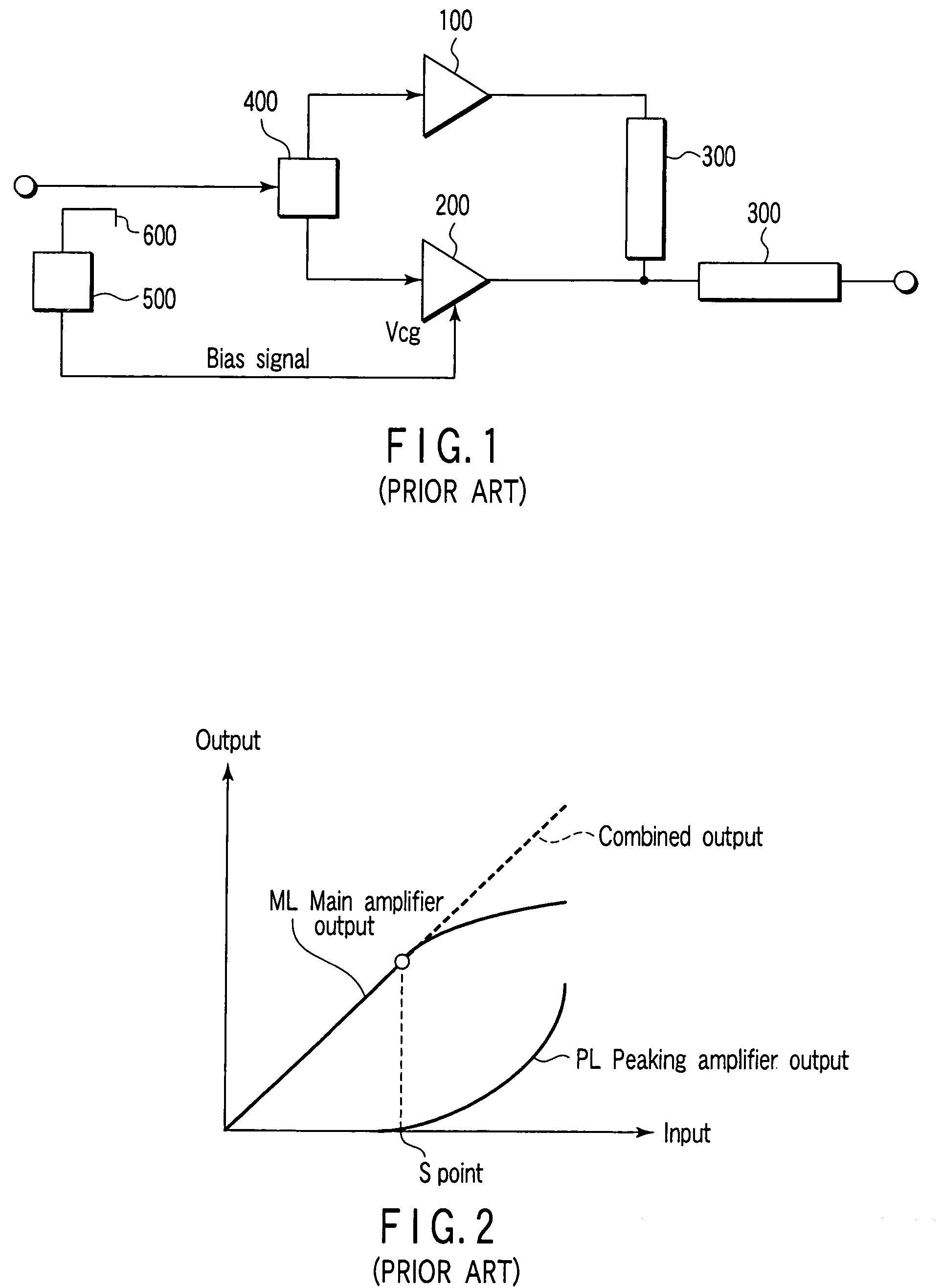
a microwave amplifier and amplifier technology, applied in the direction of amplifiers, amplifiers with semiconductor devices only, amplifiers with semiconductor devices, etc., can solve the problems that the existing doherty amplifier cannot accurately perform linear compensation, and cannot achieve accurate linearity
- Summary
- Abstract
- Description
- Claims
- Application Information
AI Technical Summary
Benefits of technology
Problems solved by technology
Method used
Image
Examples
first embodiment
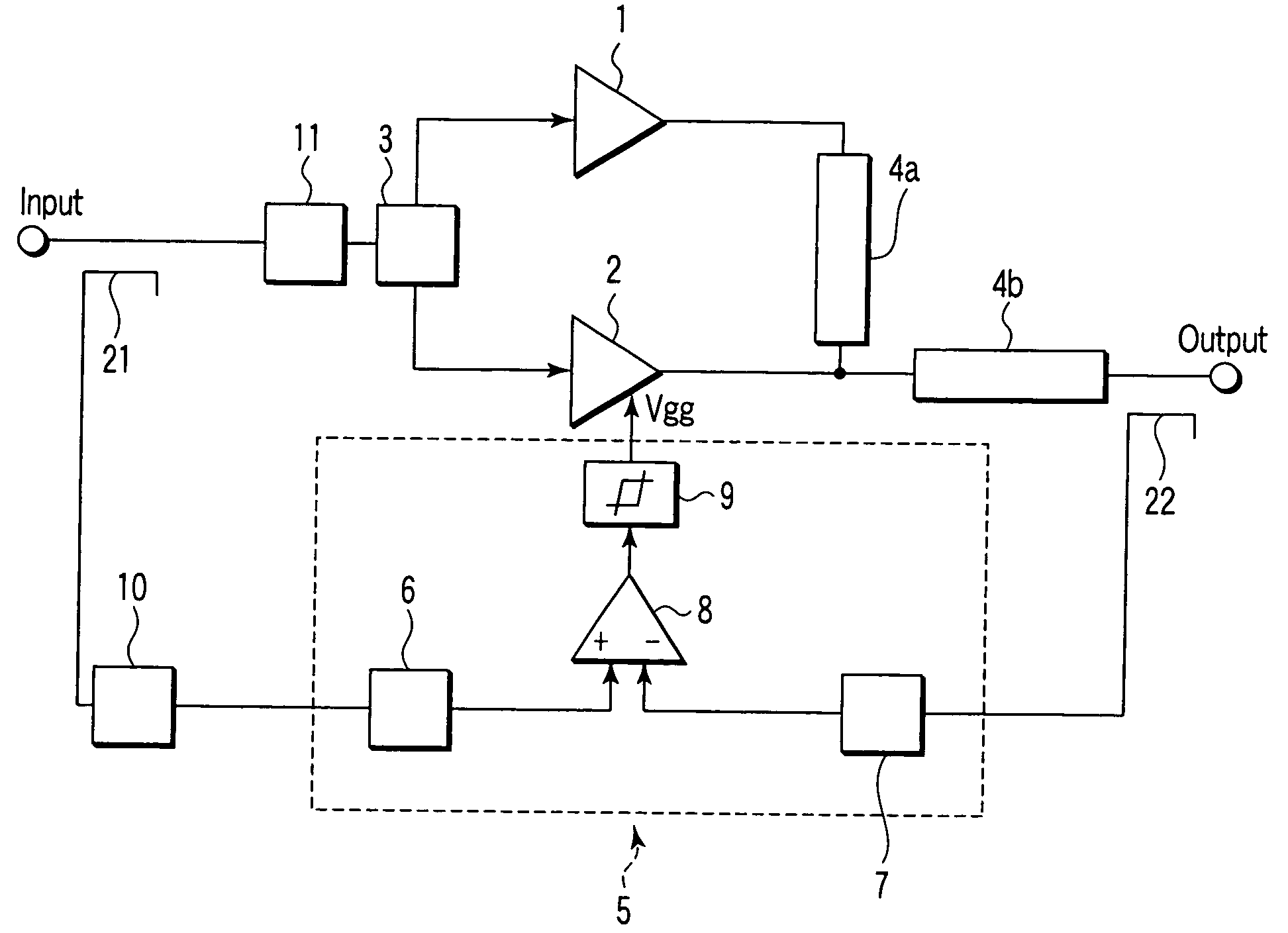
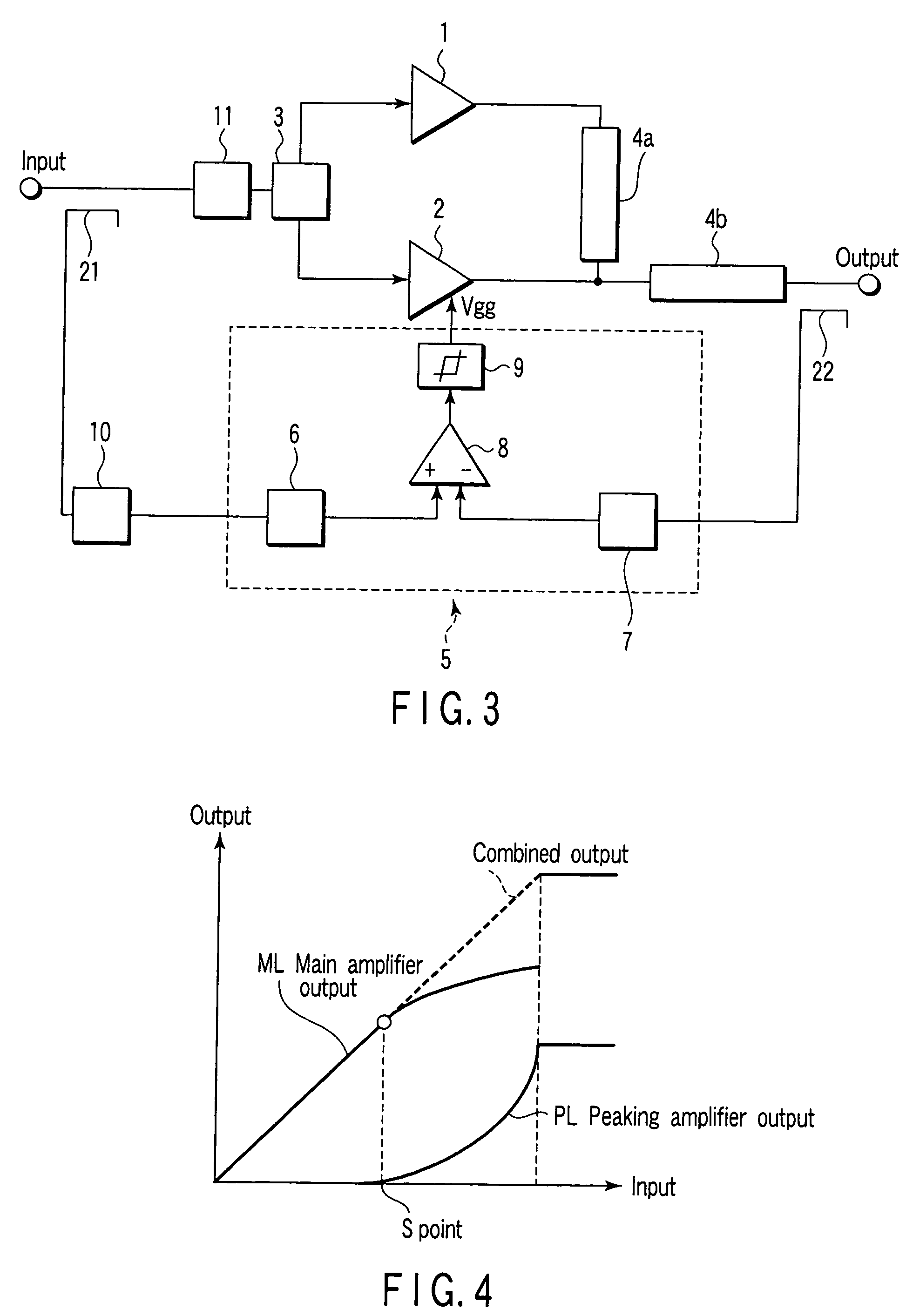
[0025]FIG. 3 is the exemplary block diagram showing the first embodiment of the Doherty amplifier regarding the present invention. FIG. 4 is the exemplary view showing the input / output characteristic of the Doherty amplifier in FIG. 3. A configuration and an operation of the Doherty amplifier regarding the first embodiment of the present invention will be described by referring to FIG. 3 and FIG. 4.
[0026]In FIG. 3, the Doherty amplifier comprises a main amplifier 1, a peaking amplifier 2, a distributor 3, a ¼ wave length impedance converter 4a, a ¼ wave length impedance converter 4b, a bias control unit 5, a delay unit 10 and a temperature compensation attenuator 11. The bias control unit 5 comprises a detector 6, a detector 7, a level comparator 8 and an amplitude limiter 9. An input and an output are provided with couplers 21 and 22 in order to branch each signal to the level comparator 8, respectively.
[0027]In the Doherty amplifier regarding the first embodiment, the level compar...
second embodiment
[0039]FIG. 5 the exemplary block diagram showing the second embodiment of the Doherty amplifier regarding the present invention. FIG. 6 is the exemplary view showing the input / output characteristic of the Doherty amplifier in FIG. 5. The Doherty amplifier in FIG. 5 comprises peaking amplifiers 2a and 2b. A bias control unit 5 comprises level comparators 8a and 8b, amplitude limiters 9a and 9b and a ¼ wave length impedance converter 4c.
[0040]The ¼ wavelength impedance converter 4c connected to the output from the peaking amplifier 2b is further added to the output of the ¼ wavelength impedance converter 4b of the peaking amplifier 2a. Therefore, the output form the Doherty amplifier becomes the combined output of the main amplifier 1 and two peaking amplifiers 2a and 2b.
[0041]In the second embodiment, the combined output is input to the level comparator 8b through the detector 7. The level comparator 8b outputs a gate voltage Vggb to the peaking amplifier 2b and one input terminal ...
third embodiment
[0049]The first embodiment of the present invention can realize a high-efficiency amplifier superior to amplitude linearity. The second embodiment of the present invention can realize a Doherty type high-efficiency amplifier capable of retain a response time in high by a parallel use of low-output peaking amplifiers 2.
[0050]In the meantime, it is important for a high-frequency such as a microwave to retain constant in not only a response time but also a phase characteristic in accordance with an output. Therefore, in the third embodiment of the present invention, a configuration capable of obtaining an output with a constant phase characteristic even if not only an amplitude characteristic but also an output amplitude have changed (in other word, change in input amplitude) will be described.
[0051]FIG. 7 is the exemplary block diagram showing the third embodiment of the Doherty amplifier regarding the present invention. The Doherty amplifier in FIG. 7 has a configuration in which a v...
PUM
 Abstract
Description
Claims
Application Information
 - R&D
- Intellectual Property
- Life Sciences
- Materials
- Tech Scout
- Unparalleled Data Quality
- Higher Quality Content
- 60% Fewer Hallucinations
Browse by: Latest US Patents, China's latest patents, Technical Efficacy Thesaurus, Application Domain, Technology Topic, Popular Technical Reports.
© 2025 PatSnap. All rights reserved.Legal|Privacy policy|Modern Slavery Act Transparency Statement|Sitemap|About US| Contact US: help@patsnap.com


