Electric part handling device

a technology for handling devices and electric parts, which is applied in the direction of transportation and packaging, manufacturing tools, and so on, can solve the problems of dead angle obstructing the view of the part and the installation position of the part, and the efficiency of the conventional device for mounting or installing an electric part is inferior, so as to minimize the dead angle and facilitate the delicate positioning of the electric par

Active Publication Date: 2007-09-18
HAKKO CO LTD
View PDF8 Cites 15 Cited by
  • Summary
  • Abstract
  • Description
  • Claims
  • Application Information

AI Technical Summary

Benefits of technology

[0009]It is another object of the present invention to provide a handheld tweezer-type device which enables delicate positioning of an electric part on a substrate upon installation of the part.
[0010]It is further object of the present invention to provide a handheld tweezer-type heating device which minimizes the dead angl...

Problems solved by technology

The conventional device is inferior in efficiency of operation for mounting or installing an electric part, since it requires the operator to exert a large force for closing the legs against the force of the spring and holding the electric part between the tips while holding the device.
Especially, it is difficult for the operator to position and install a small electric part on a substrate since the operator is requi...

Method used


Image

  • Electric part handling device
  • Electric part handling device
  • Electric part handling device

Examples


Embodiment Construction

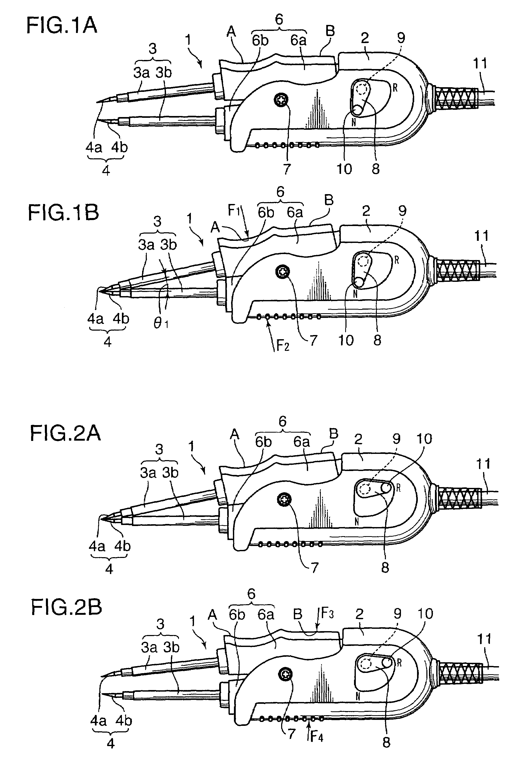
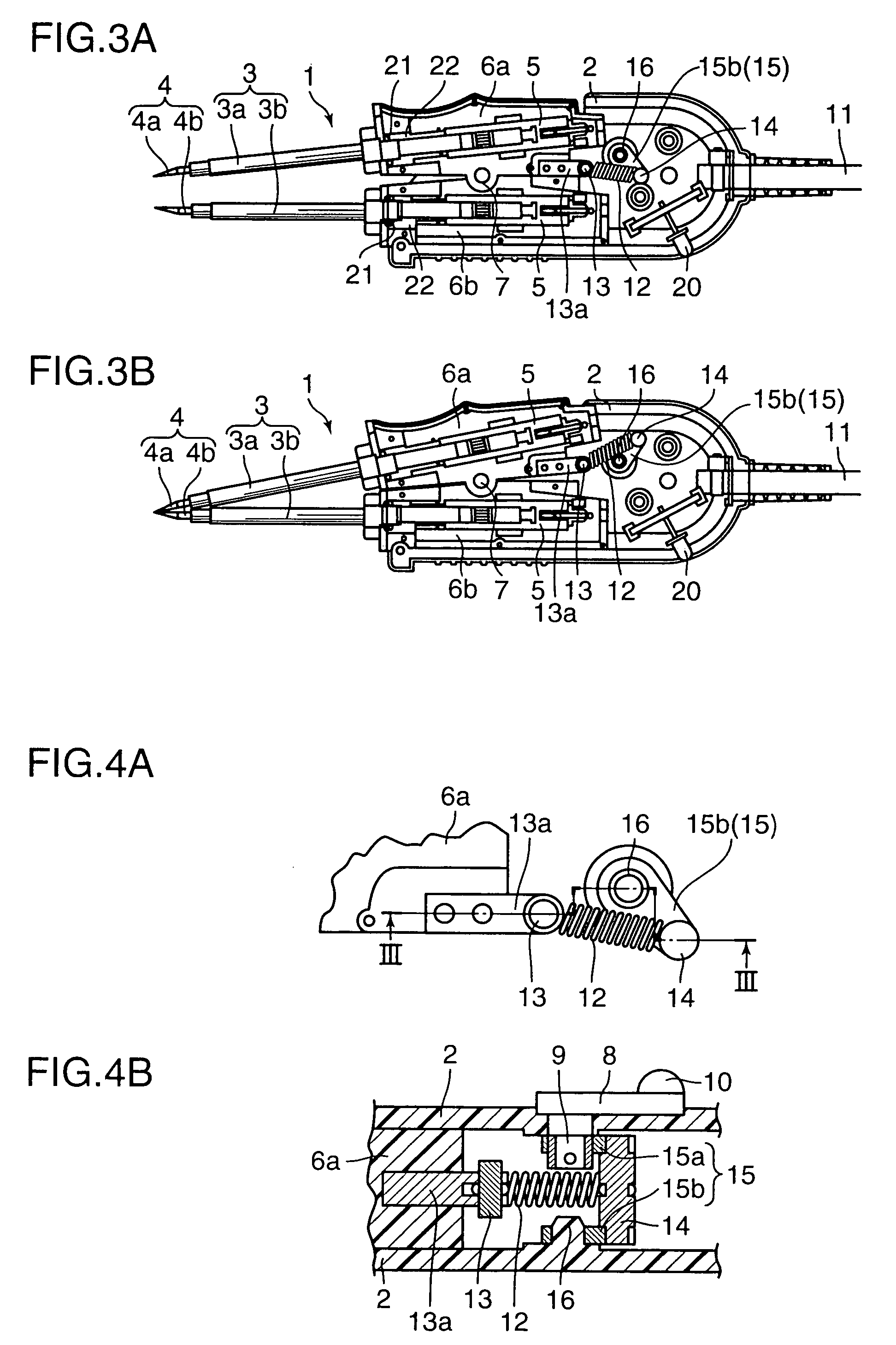
[0028]Description will be made of an embodiment of the present invention with reference to the accompanying drawings wherein like reference characters and numerals refer to like parts. FIGS. 1 and 2 show a hand-held tweezer type electric part installing and / or removing device 1 according to an embodiment of the present invention. The device 1 has a pair of legs 3 (3a and 3b) which are biased to open in a normal bias condition of the device 1 such that the legs assume open positions as shown in FIG. 1A in a free condition when no operating force is exerted to the device 1. In a reverse bias condition of the device 1 as shown in FIG. 2A, the legs 3 are biased to close in a free condition when no operating force is exerted to the device 1. Referring to FIGS. 1 and 2, FIGS. 1A and 2A respectively show free condition of the device 1, while FIGS. 1B and 2B respectively show operated or manipulated condition of the device 1 where an operating force is exerted to the device 1 by an operator...


PUM

PropertyMeasurementUnit
Angleaaaaaaaaaa
Angleaaaaaaaaaa
Angleaaaaaaaaaa

Abstract

A tweezer-type hand-held device for installing and removing an electric part on and from a substrate. The device is provided with a pair of legs biased to close such that the part is held between the legs by the biasing force when the part is installed on the substrate. In an embodiment, one of the legs may be biased in two directions, i.e. in a direction to open and in another direction to close, and a switching member is disclosed to switch the biasing direction. The biasing member may include a spring commonly used for the biasing in the two directions. Manipulation portions are provided for open or close the legs against the force of the biasing member.

Description

CROSS-REFERENCE TO RELATED APPLICATIONS[0001]This application is based on Japanese patent application serial No. 2003-110146, filed in the Japan Patent Office on Apr. 15, 2003, the contents of which are hereby incorporated by reference.BACKGROUND OF THE INVENTION[0002]1. Field of the Invention.[0003]The present invention relates to a device for handling an electric part such as resistor, capacitor and IC, and more particularly pertains to a hand-held tweezer type device for holding the electric part between a pair or legs. The device may be used for heating and reflowing solder at joints between the part and the substrate to solder or desolder the part and holding the part between a pair of legs to install or remove the part on or from a substrate. It is to be noted that the term electric part include not only ordinary electric part such as a resistor and capacitor but also electronic part such as transistor, diode and IC.[0004]2. General Background and State of the Art.[0005]Known ...

Claims


Application Information

Patent Timeline
IPC IPC(8): B23P19/00B23K3/02B23K3/03B23K3/08B25B27/00H05K3/34H05K13/04
CPCB23K3/0369B23K3/08H05K13/0447H05K13/0491B23K2201/40Y10T29/5313Y10T29/53174Y10T29/53222Y10T29/53257Y10T29/53213B23K2101/40
Inventor MIYAZAKI, MITSUHIKO
Owner HAKKO CO LTD
Why Eureka
Try Eureka