
Frequency offset correction in transmitters having non-ideal synthesizer channel spacing

a frequency offset correction and channel spacing technology, applied in the field of signal processing, can solve the problem that the reference oscillator of the synthesizer often needs to be phase-locked

Inactive Publication Date: 2007-09-18
COMMSCOPE TECH LLC
View PDF4 Cites 3 Cited by
  • Summary
  • Abstract
  • Description
  • Claims
  • Application Information

AI Technical Summary

Benefits of technology

This approach allows for accurate signal processing and reduced errors in both receivers and transmitters, eliminating the need for additional oscillators and improving operational efficiency by using the system clock as the reference for synthesizers, thus maintaining acceptable bit error rates and frequency accuracy.

Problems solved by technology

An additional complication is that the reference oscillator for the synthesizer often needs to be phase-locked to the system clock.

Method used


Image

  • Frequency offset correction in transmitters having non-ideal synthesizer channel spacing
  • Frequency offset correction in transmitters having non-ideal synthesizer channel spacing
  • Frequency offset correction in transmitters having non-ideal synthesizer channel spacing

Examples


Embodiment Construction

Receiver

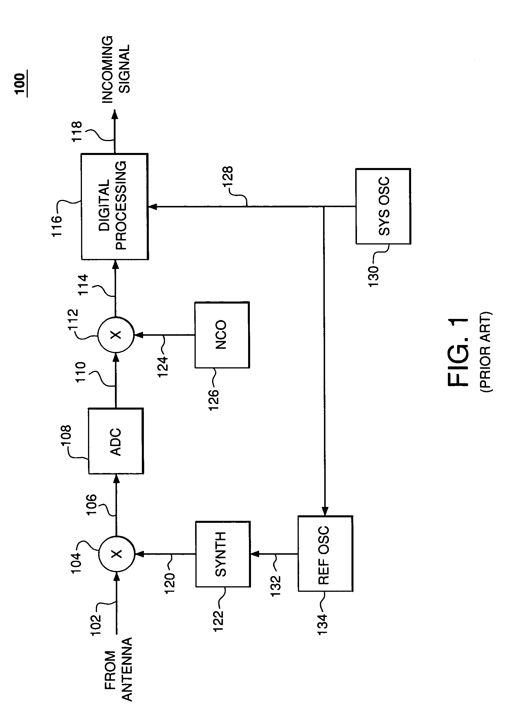
[0017]FIG. 3 shows a high-level block diagram of a radio receiver 300, according to one embodiment of the present invention. Receiver 300 is similar to prior-art receiver 100 of FIG. 1, with corresponding elements 302-330 performing similar functions as elements 102-130 of FIG. 1, except that receiver 300 does not have a dedicated reference oscillator similar to reference oscillator 134 of receiver 100. Rather, in receiver 300, synthesizer 322 is driven directly by system clock signal 328 generated by system oscillator 330.

[0018]In the same possible application as the one described previously for receiver 100, receiver 300 is designed and tuned to operate for any channel in RF input signal 302 having a frequency from 1920 MHz to 1980 MHz in 200-kHz increments. As in receiver 100, in order to downconvert RF input signal 302 to IF, mixer 304 applies a mixing signal 320 generated by synthesizer 322. In receiver 300, however, synthesizer 322 uses 61.44-MHz system clock signal 32...


PUM


Abstract

In a receiver of a transmission system in which the data transmission rate is not an integer multiple of the spacing between transmission channels, a single oscillator is used to generate both the system clock used to process the data signal as well as the mixing signal used to downconvert the received RF signal to an intermediate frequency (IF). The frequency error in the IF signal that results from mixing the RF signal at a less-than-ideal mixing frequency is compensated by selecting an appropriate mixing signal frequency applied when downconverting the IF signal to baseband. In a transmitter, the mixing signal frequency used to upconvert the outgoing baseband signal to IF is selected to pre-compensate for the frequency error resulting from upconverting the IF signal to RF using a less-than-ideal mixing frequency. In either case, the receiver / transmitter can be implemented without having to provide a dedicated reference oscillator for converting signals between RF and IF.

Description

FIELD OF THE INVENTION[0001]The present invention relates to signal processing, and, in particular, to radio transmitters and receivers.BACKGROUND OF THE INVENTION[0002]In conventional radio transmitters and receivers used for data communications, the reference clock frequency used by a synthesizer is an integer multiple of the channel spacing or frequency tuning raster for the communications system. Such radio transmitters and receivers typically have a system clock for digital clocking purposes, but the system clock's frequency is usually related to the data transmission rate and is often not an integer multiple of the channel spacing (i.e., the system clock frequency and the synthesizer's phase detector frequency have a non-integer relationship). In that case, another oscillator is added solely to provide a reference clock for the synthesizers. An additional complication is that the reference oscillator for the synthesizer often needs to be phase-locked to the system clock.[0003]...

Claims


Application Information

Patent Timeline
Patent Type & Authority Patents(United States)
IPC IPC(8): H04B1/02H04B1/66H03D7/16H03J1/00H04B1/04H04B1/26H04B1/40H04B15/00H04L25/03
CPCH03J1/005H03D7/161
Inventor CLEARY, DENNISPAGANO, CARMINEPENSO, HAYIM VITALIRUCKI, JOHN
Owner COMMSCOPE TECH LLC
Learn More