Shower screen

a technology of shower screen and screen member, which is applied in the direction of wing accessories, corner/edge joints, wing arrangements, etc., can solve the problems of side beams and the screen member also not being stably anchored or coupled to the lower guide bar

Inactive Publication Date: 2007-09-25
CHEN CHANG THAN
View PDF12 Cites 25 Cited by
  • Summary
  • Abstract
  • Description
  • Claims
  • Application Information

AI Technical Summary

Benefits of technology

[0009]The primary objective of the present invention is to provide a shower screen including a solidly and smoothly anchoring structure for coupling and retaining foldable panels of a screen member.
[0010]In accordance with one aspect of the invention, there is provided a shower screen comprising a pair of vertical posts each including a longitudinal channel formed therein, and each including a lower portion, an upper guide rod secured on top of the posts, a screen member including a number of panels foldably coupled together with foldable hinges, and each having an upper portion slidably attached to the guide rod, for allowing the panels to be folded to a folding position and to be unfolded to an open and working position, the screen member including two side portions and including a lower portion, two beams secured to the side portions of the screen member respectively, and each including a protrusion extended outwardly therefrom, for engaging into the channels of the posts respectively, and for retaining the panels of the screen member in the open and working position, to prevent spilling while showering, the beams each including a lower portion, a lower guide bar secured to the lower portions of the posts, and including an outer wall extended upwardly therefrom, an upper wall extended laterally from the outer wall, and an inner wall extended downwardly from the upper wall, to form and define a downwardly facing passage therein. The beams each includes a hook member secured to the lower portion thereof and having an upwardly extending projection provided thereon, to slidably engage into the passage of the guide bar, and to anchor the lower portions of the beams to the guide bar, and to prevent the lower portions of the beams from fluctuating relative to the guide bar, and at least one hook device is attached to the lower portion of the screen member, and includes an upwardly extending projection provided thereon, to slidably engage into the passage of the guide bar, and to anchor the lower portion of the screen member to the guide bar, and to prevent the lower portion of the screen member from fluctuating relative to the guide bar. It is to be noted that the hook members and the hook devices may stably couple the lower portions of the screen member and the beams to the lower guide bar, such that the lower portions of the screen member and the beams will not be moved or fluctuated or vibrated relative to the lower guide bar.

Problems solved by technology

However, the side beams may not be stably anchored or coupled to the lower guide bar, and may move or fluctuate relative to the lower guide bar.
However, the retaining members of the side beams are also simply contacted with the lower guide bar, and the foldable panels of the screen member may also move or fluctuate relative to the lower guide bar, such that the screen member also may not be stably anchored or coupled to the lower guide bar.

Method used


Image

  • Shower screen
  • Shower screen
  • Shower screen

Examples


Embodiment Construction

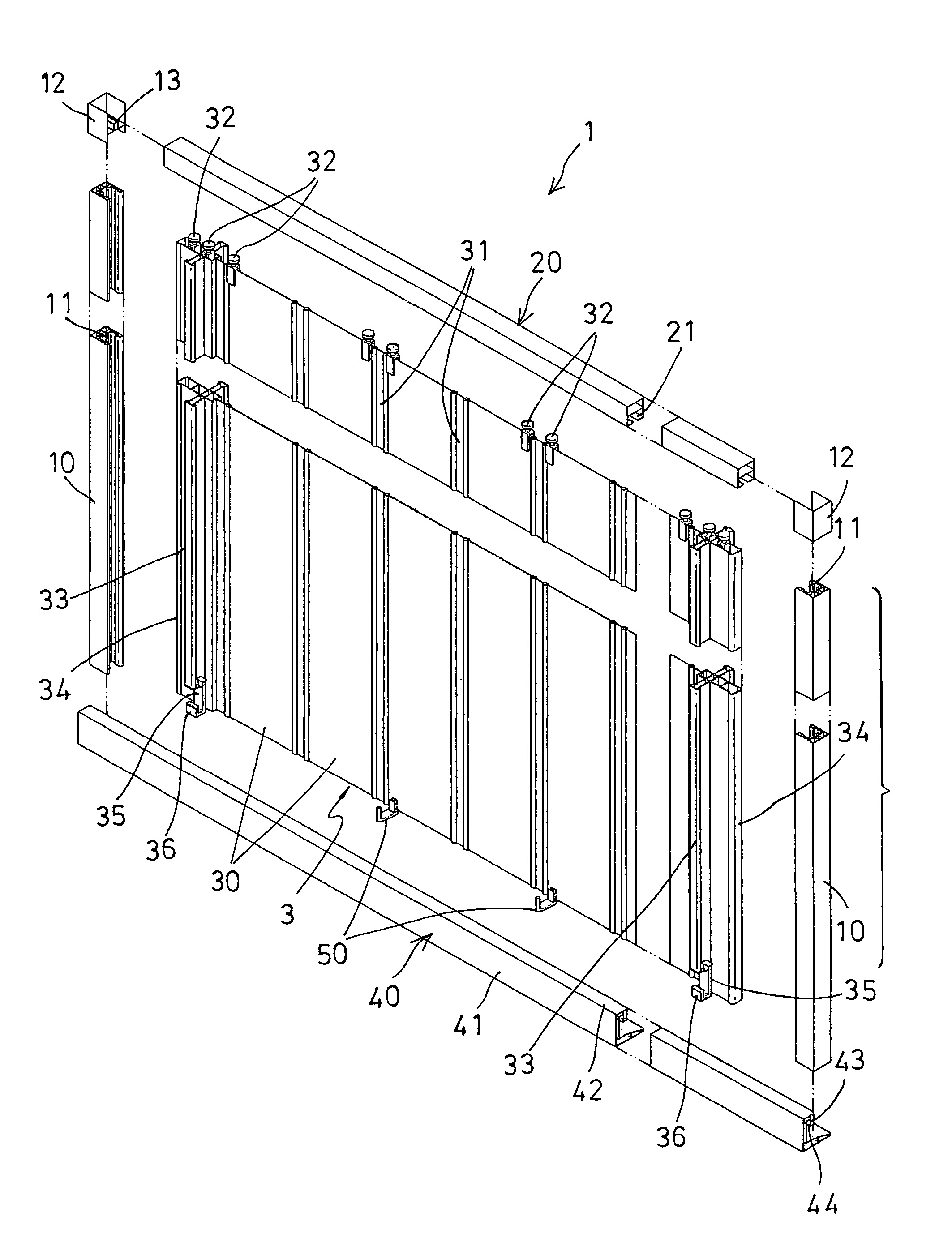
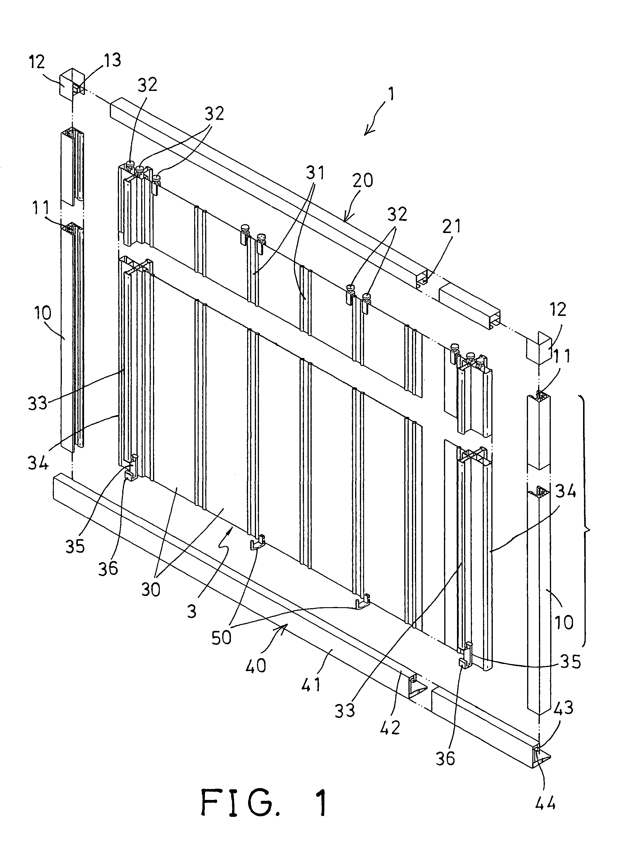
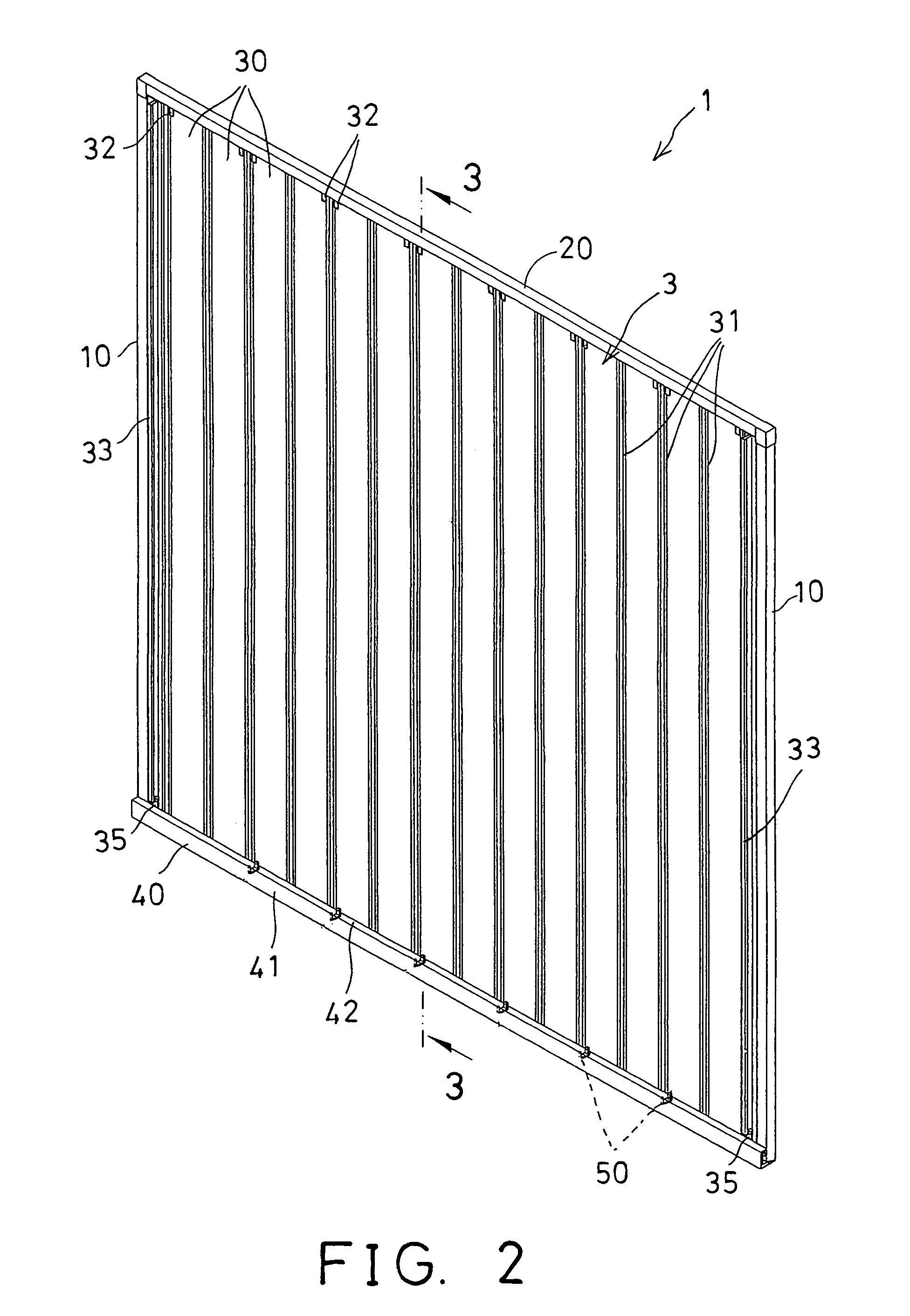
[0020]Referring to the drawings, and initially to FIGS. 1-3, a shower screen 1 in accordance with the present invention comprises a pair of vertical posts 10 each including a longitudinal channel 11 formed therein and facing toward each other. Two brackets 12 are secured on top of the posts 10 respectively, and each includes a key 13 provided therein (FIG. 1).

[0021]An upper guide rod 20 includes two end portions engaged in or attached to the brackets 12, and includes a groove 21 formed in the lower portion thereof and having two ends engaged with the respective keys 13, for anchoring and securing or coupling the guide rod 20 to the posts 10 with the brackets 12, and for preventing the guide rod 20 from rotating relative to the brackets 12 and the posts 10.

[0022]A screen member 3 includes a number of panels 30 foldably secured or coupled together with foldable lines or hinges 31, for allowing the panels 30 to be folded relative to each other to form a zigzag shape. Each of the panels...


PUM


Abstract

A shower screen includes an upper guide rod secured on top of two posts, a screen member having a number of panels foldably coupled together and having an upper portion slidably attached to the guide rod, and two beams secured to sides of the screen member. A lower guide bar is secured to lower portions of the posts, and includes a downwardly facing passage. The beams and the screen member each includes a hook member or hook device having a projection slidably engaged into the passage of the guide bar, to anchor the lower portions of the beams and the screen member to the guide bar, and to prevent the beams and the screen member from fluctuating or vibrating relative to the guide bar.

Description

BACKGROUND OF THE INVENTION[0001]1. Field of the Invention[0002]The present invention relates to a shower screen, and more particularly to a shower screen having a solidly and smoothly anchoring structure for coupling and retaining foldable panels of a screen member.[0003]2. Description of the Prior Art[0004]The applicant has developed various kinds of typical shower screens and comprise a guide rod and a guide bar secured between top and lower portions of two spaced side posts, and a screen member having a number of foldable panels foldably and slidably attached between the guide rod and the guide bar.[0005]For example, U.S. Pat. No. 5,822,810 to Chen discloses one of the typical shower screens which also comprise a screen member having a number of foldable panels foldably and slidably attached between a guide rod and a guide bar that are secured between top and lower portions of two spaced side posts, and two side beams attached to side portions of the panels.[0006]The side beams ...

Claims


Application Information

Patent Timeline
Patent Type & Authority Patents(United States)
IPC IPC(8): E05D15/26
CPCA47K3/362
Inventor CHEN, CHANG THAN
Owner CHEN CHANG THAN
Why Eureka
Try Eureka