Universal electrical module

a universal electrical module and electrical module technology, applied in the direction of coupling device connection, coupling base/case, tumbler/rocker switch details, etc., can solve the problem of laborious installation of each electrical device, reduce and reduce the time required to install electrical devices. , the effect of reducing the time and skill level

Inactive Publication Date: 2007-09-25
FIELDS DAN
View PDF9 Cites 76 Cited by
  • Summary
  • Abstract
  • Description
  • Claims
  • Application Information

AI Technical Summary

Benefits of technology

[0015]A primary advantage of the present invention to significantly reduce the time required to install electrical devices in a building after wallboard application.
[0016]Another advantage of the present invention is to reduce the time and skill level required to install electrical devices in a building, or for changing over from one type of device to another.
[0017]A further advantage of the present invention is to provide for the availability of power in a building structure during the framing stage without undue risk to the working personnel.
[0018]Yet another advantage of the present invention is to enable a safer installation of electrical devices during building construction or remodeling.
[0019]Still another advantage of the present invention is to provide for single or multiple gang modules having a single point of connection to a power, neutral, and ground source.
[0020]These and other advantages of the present invention will become apparent from a reading of the following description, and may be realized by means of the instrumentalities and combinations particularly pointed out in the appended claims.

Problems solved by technology

The installation of each electrical device is a laborious task that is generally performed by hand by a trained electrician.

Method used


Image

  • Universal electrical module
  • Universal electrical module
  • Universal electrical module

Examples


Embodiment Construction

[0037]Detailed descriptions of embodiments of the invention are provided herein. It is to be understood, however, that the present invention may be embodied in various forms. Therefore, the specific details disclosed herein are not to be interpreted as limiting, but rather as a representative basis for teaching one skilled in the art how to employ the present invention in virtually any detailed system, structure, or manner.

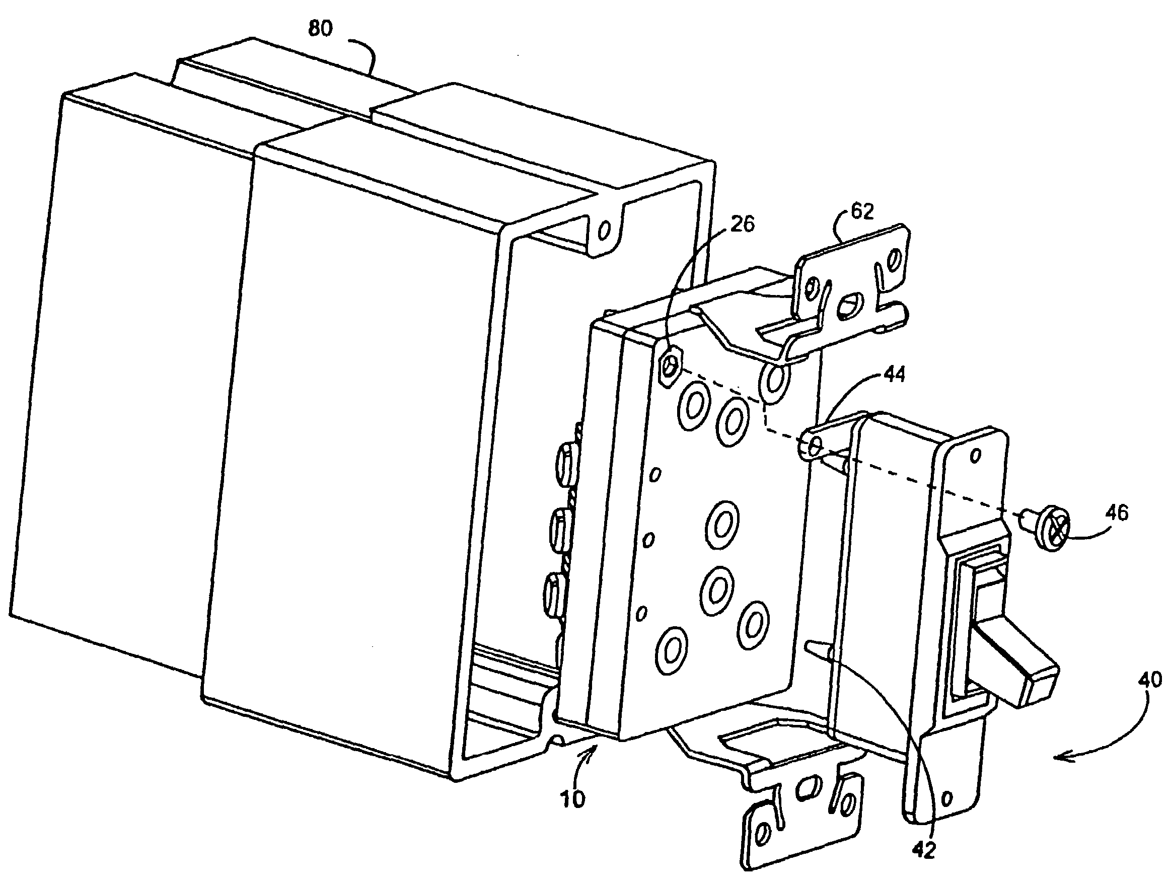
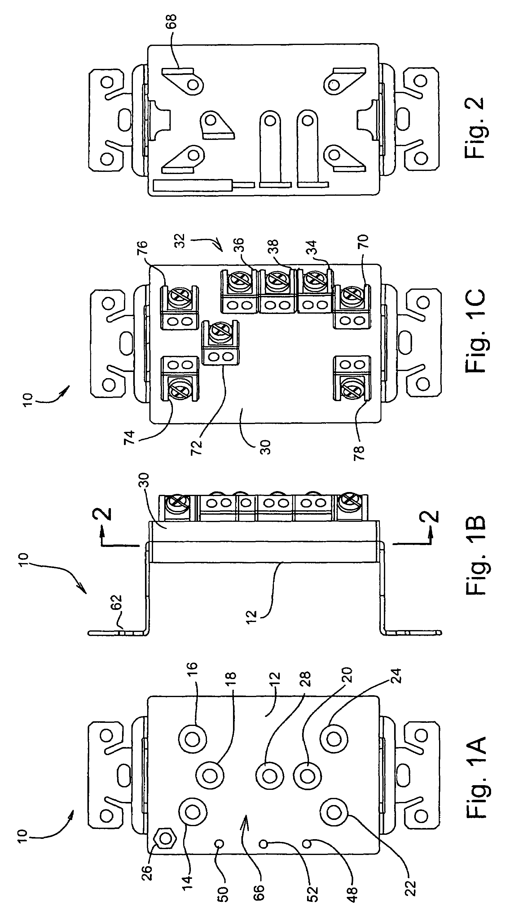
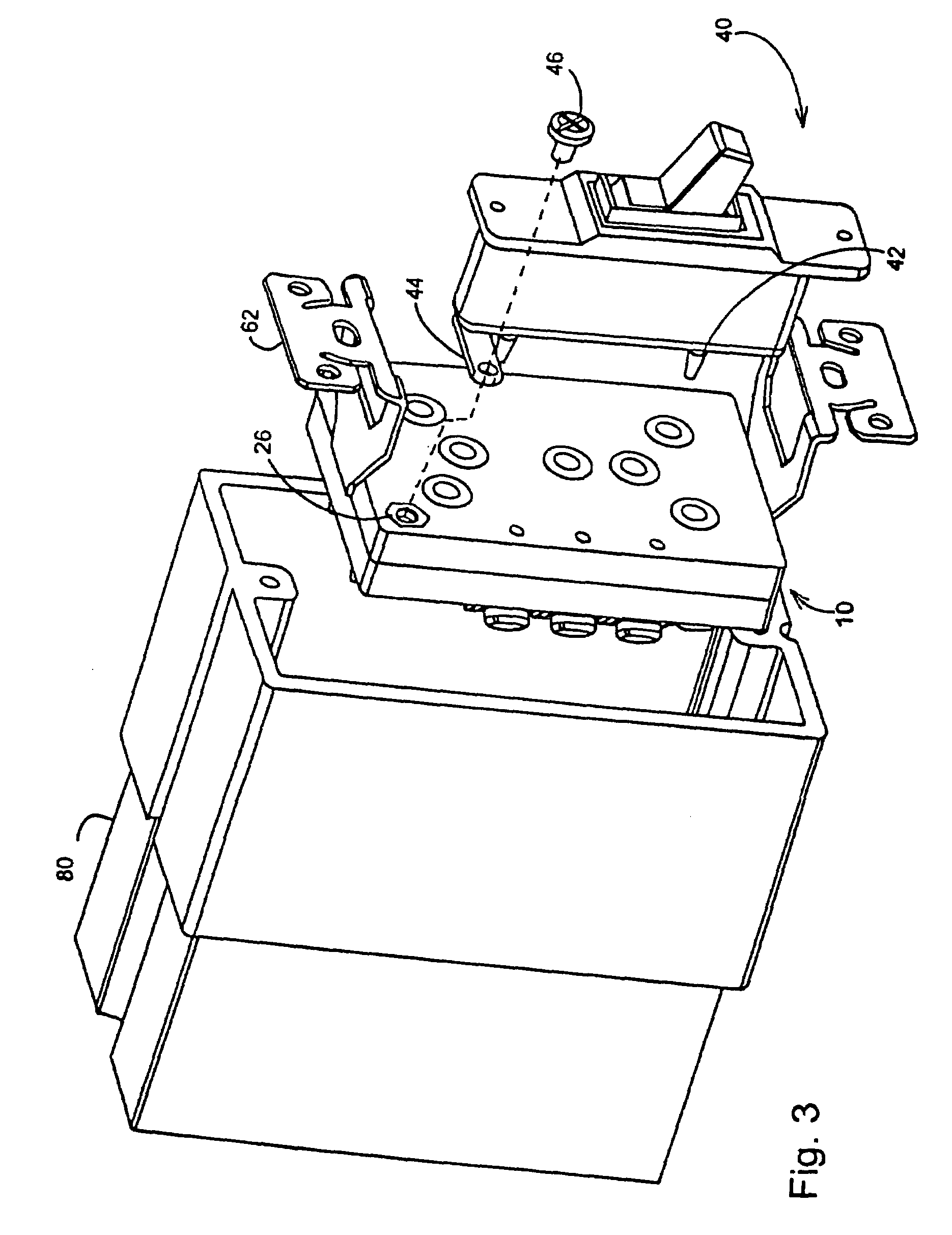
[0038]In accordance with one embodiment of the present invention, there are shown in FIGS. 1A-1C different views of a single gang universal electrical module 10 that is designed for positioning inside an electrical box. More specifically, FIG. 1A illustrates a front view of module 10, FIG. 1B illustrates a left side view, and FIG. 1C illustrates a rear view.

[0039]Module 10 comprises a front face 12, a rear face 30, and two retention plates 62 enabling the permanent positioning of module 10 into an electrical box. A plurality of slots, indicated with reference nume...


PUM


Abstract

In one embodiment, a universal electrical module is provided that facilitates the quick and safe installation of different types of electrical devices in an electrical box by enabling a technician to simply insert prongs extending from the electrical devices into matching slots on a first face of the universal electrical module. The universal electrical module is connected to the hot, ground and neutral wires of the building circuit by means of a bus on a second face of the module, and may be produced in different sizes to support one or more electrical devices. Additionally, meter reading slots may be provided on the first face to enable meter reading from the front face of the module. In another embodiment, an electrical device is provided that comprises a plurality of prongs extending from the device, wherein each of the prongs is structured to mate with a slot on an electrical module.

Description

CROSS-REFERENCE TO RELATED APPLICATIONS[0001]The present patent application claims priority to provisional patent application Ser. No. 60 / 592,256 filed on Jul. 29, 2004 and titled “Universal Electrical Module.”BACKGROUND OF THE INVENTION[0002]1. Field of the Invention[0003]The present invention relates to a universal electrical module that improves ease and speed of installation of electrical devices during building construction. More specifically, the present invention relates to a universal electrical module that facilitates the installation of different types of an electrical device by enabling a technician to simply insert prongs that extend from each of the electrical devices into matching slots on the universal electrical module.[0004]2. Description of Related Art[0005]In the building industry, electrical boxes are typically installed during the framing of the building structure. Conduits such as electrical wires are drawn to the electrical boxes after the boxes are installed ...

Claims


Application Information

Patent Timeline
Patent Type & Authority Patents(United States)
IPC IPC(8): H01R13/60
CPCH01R25/00
Inventor FIELDS, DAN
Owner FIELDS DAN
Why Eureka
Try Eureka