Supercharge Your Innovation With Domain-Expert AI Agents!

Plasma display panel having bumps on barrier ribs

a technology of barrier ribs and plasma display panels, which is applied in the manufacture of electrode systems, cold cathode manufacturing, electric discharge tubes/lamps, etc., can solve the problems of difficult combination of front substrates, high cost of front substrates b>120/b>, and many problems, and achieves the effect of simple process

Inactive Publication Date: 2007-09-25
CHUNGHWA PICTURE TUBES LTD
View PDF4 Cites 2 Cited by
  • Summary
  • Abstract
  • Description
  • Claims
  • Application Information

AI Technical Summary

Benefits of technology

"The present invention provides a plasma display panel with a simple manufacturing process that overcomes problems of previous methods. The panel includes a first substrate with electrodes and a grid-mesh-shaped barrier rib formed on the electrodes. The barrier rib has bumps and channels that allow air to flow in the discharge space and from the passages. The method of manufacturing the panel includes screen print using a vacuum hole and a first substrate with electrodes. The screen print is applied to form the channels and bumps on the first substrate. The second substrate is combined with the first substrate to close the discharge space and air can flow from the passages to the channels and from the channels to the vacuum hole. The screen print method is cost-effective and efficient in using material."

Problems solved by technology

Several problems have been encountered by the conventional method.
Firstly, the front substrate 120 is expensive because it has to form a grid-mesh-shaped barrier rib 121.
Secondly, it is difficult to combine the front substrate 120 with the rear substrate 110 since they must be precisely aligned.
Some problems also have been encountered.
Firstly, the front substrate 170 is expensive since it needs to form the bumps 171.
Secondly, it is difficult to combine the front substrate 170 with the rear substrate 160 since they must be aligned precisely.

Method used


Image

  • Plasma display panel having bumps on barrier ribs
  • Plasma display panel having bumps on barrier ribs
  • Plasma display panel having bumps on barrier ribs

Examples


Embodiment Construction

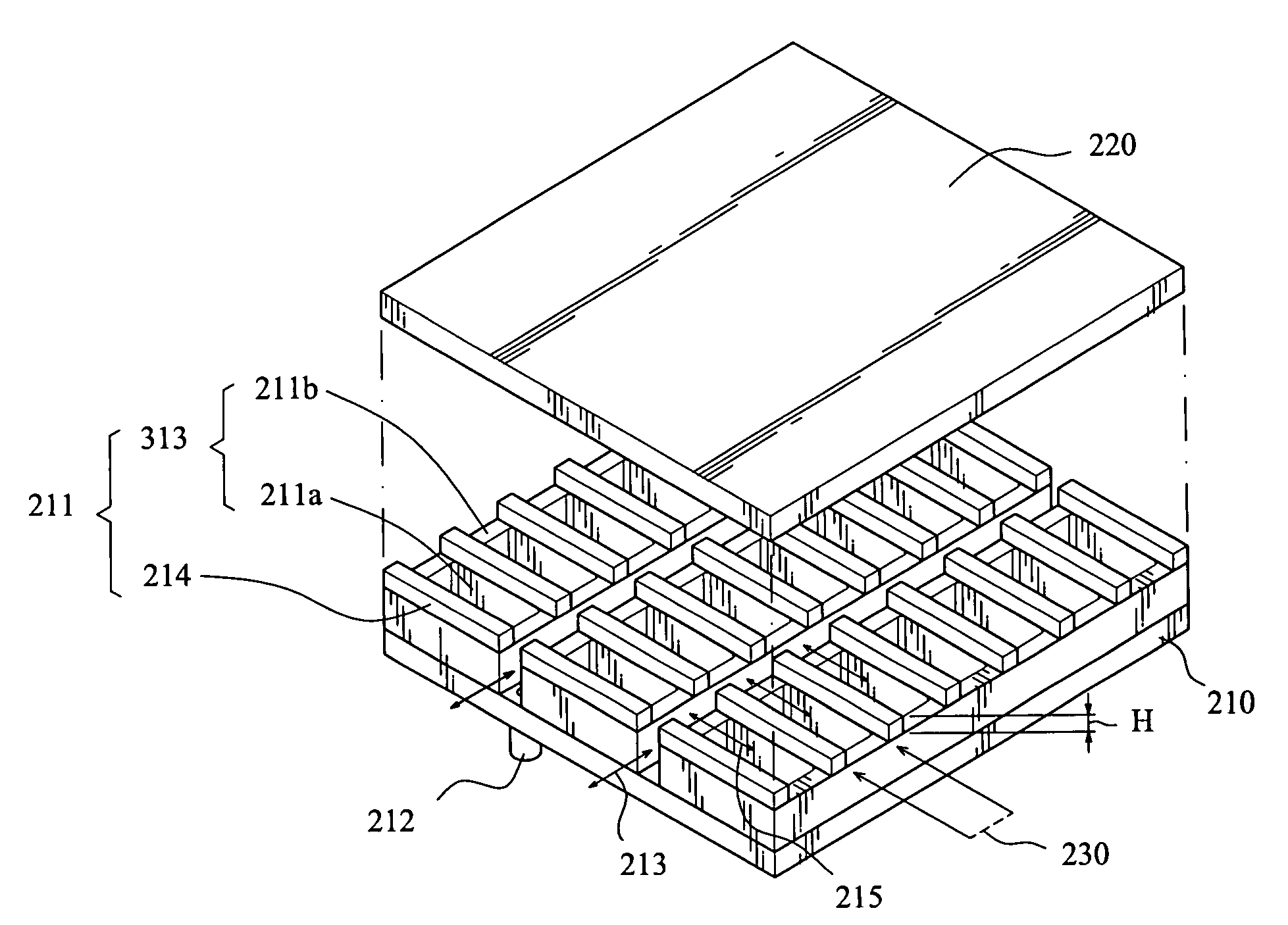
[0022]As shown in FIG. 2, the plasma display panel includes a first substrate 210 and a second substrate 220 paralleled with the first substrate 210 so as to define a discharge space. A vacuum hole 212, a plurality of elongated electrodes (not shown in the FIG. 2), and an overcoat layer are successively formed on the first substrate 210. Each elongated electrode is paralleled to a first direction (not shown in the FIG. 2) and a grid-mesh-shaped barrier rib 211 is formed on the overcoat layer. The grid-mesh-shaped barrier rib 211 of the first substrate 210 includes a plurality of first stripe ribs 211a so as to define a plurality of sub discharge spaces 230 and a plurality of second stripe ribs areas 211b intersecting the first stripe ribs 211a; each second stripe ribs 211b defines a channel 213. A vacuum hole 212 is formed on one of the channels 213, and the depth of the channels 213 is deeper than that of the discharge space. Bumps 214, which include a thickness H, are finally form...


PUM


Abstract

A plasma display panel and method are provided. The method includes that a first substrate is provided and elongated electrodes are formed on the first substrate. Then, an overcoat layer is formed on the elongated electrodes and the first substrate. Next, by means of screen print, a shaped layer is formed on the overcoat layer. Screen print is applied again to form bumps on the shaped layer. A second substrate is also provided. The second substrate is extended paralleled with the first substrate so as to define a discharge space between the substrates after combining the two substrates. Bumps are provided between the first and second stripe ribs so as to define passages to let air can flow in the discharge space. By the mentioned processes, bumps are provided between the first and second stripe ribs so as to define passages for drawing air. The process is simple for alignment.

Description

BACKGROUND OF THE INVENTION[0001]1. Field of the Invention[0002]The present invention relates to a plasma display panel and a method for making the same and, more particularly, to a grid-mesh-shaped barrier rib structure of the plasma display panel and a method for making the same.[0003]2. Description of the Related Art[0004]Most barrier rib structures of plasma display panel are a strip-shaped or a grid-mesh-shaped. As shown in FIG. 1, a perspective view of a conventional plasma display panel. A strip-shaped barrier rib 111 is formed on a rear substrate 110 and a grid-mesh-shaped barrier rib 121 is formed on a front substrate 120. And then combine the front substrate 120 with the rear substrate 110 to a plasma display panel 100. Several problems have been encountered by the conventional method.[0005]Firstly, the front substrate 120 is expensive because it has to form a grid-mesh-shaped barrier rib 121. Secondly, it is difficult to combine the front substrate 120 with the rear subst...

Claims


Application Information

Patent Timeline
Patent Type & Authority Patents(United States)
IPC IPC(8): H01J17/49
CPCH01J9/242H01J11/12H01J11/36H01J2211/365
Inventor CHEN, YU-SHENGLEU, CHIH-HSIUNGCHOU, CHUNG-WANG
Owner CHUNGHWA PICTURE TUBES LTD
Features
  • R&D
  • Intellectual Property
  • Life Sciences
  • Materials
  • Tech Scout
  • Unparalleled Data Quality
  • Higher Quality Content
  • 60% Fewer Hallucinations
Learn More