Mirror reflective element assembly

a technology of mirror reflective elements and components, applied in the direction of mirrors, mountings, instruments, etc., can solve the problems of limited display size and quantity, loss of reflectivity in the window area, corrosion of the metallic layer, etc., to achieve enhanced transmissivity, limit tinting and/or color interference, and low cost

Inactive Publication Date: 2007-09-25
DONNELLY CORP
View PDF134 Cites 531 Cited by
  • Summary
  • Abstract
  • Description
  • Claims
  • Application Information

AI Technical Summary

Benefits of technology

[0025]In one form, the electrochromic mirror assembly may include a display element positioned at the fourth surface, wherein the display element is operable to emit light through the mirror element for viewing by a driver of the vehicle. The thicknesses of the particular layers of the conductive stack are selected such that the mirror element is spectrally tuned to transmit a predetermined spectral band of light therethrough. The spectral band that is transmittable through the mirror element may be selected to match a spectral band or range of light wavelengths emitted by the display element, such that the mirror element is spectrally tuned for the particular display element positioned at the fourth surface of the mirror element. The mirror element thus may be spectrally tuned to match at least a portion of the transmissive band or range of wavelengths of the mirror element to a particular band or range of wavelengths of the light being emitted by the display element. In one form, the peak transmissivity of the transmissive band of the mirror element is selected to match the peak intensity of the spectral band emitted by the display element. The conductive stack preferably provides at least approximately 60 percent photopic reflectance (preferably as measured in accordance with Society of Automotive Engineers test procedure SAE J964a, which is hereby incorporated herein by reference in its entirety), more preferably at least approximately 70 percent photopic reflectance, and most preferably at least approximately 80 percent photopic reflectance, while providing at least approximately 10 percent transmission, preferably at least approximately 15 percent transmission, more preferably at least approximately 20 percent transmission, and most preferably at least approximately 30 percent transmission, of at least a particular spectral band of light. Preferably, the physical thicknesses of the layers are selected to limit tinting and / or color interference affects as seen in the mirror element (i.e. to provide a neutral reflector) and to spectrally tune the mirror element for a transmission characteristic for providing enhanced transmissivity through the mirror element for a particular spectral band or range of wavelengths, in order to match the transmissivity of the mirror element to the spectral band of emission of light from the display element.
[0026]The semi-conductive layers and metallic layer of the conductive stack may be deposited at the third surface via a sputter coating process. The present invention thus may provide a low cost reflective element which provides for sufficient transmission of a particular spectral band or bands of visible light and sufficient reflectance at the third surface of the mirror assembly (with at least 60% photopic reflectance preferred, more preferably, with at least 70% photopic reflectance, and most preferably, with at least 75% photopic reflectance). Preferably, the semi-conductive layers, such as indium tin oxide or the like, sandwiching the metallic layer are formed of the same material. Thus, for example, a conductive stack of alternating layers may comprise a metallic layer of silver sandwiched between two semi-conductive layers of indium tin oxide.

Problems solved by technology

However, the window defines an area of the reflective element that no longer has the reflective coating, such that reflectivity is lost in the window area.
Therefore, the size and the quantity of displays that can be provided at the mirror reflective element is limited.
However, there are concerns with the electrochromic medium of such mirror assemblies contacting the metallic layer, since chemical and / or electro-chemical attack on the metallic layer may result in corrosion of the metallic layer.
However, such designs have layers or coatings that are relatively thin (often less than 150 Å or thereabouts in thickness) and so any variation in metallic layer thickness may lead to a significant variation in light transmission through such thin metallic coatings.
Such tolerances and uniformity may be difficult to achieve through sputter coating or other coating processes typically used in the manufacture of such reflective elements.
Therefore, such significantly thin metallic coatings may be difficult and costly to manufacture.
The illumination sources and imaging device cannot typically be positioned within the mirror casing due to the difficulties encountered in projecting light or illumination through the reflective element to the cabin and allowing light from within the cabin to pass through the reflective element to the imaging device.
Typically, such transmissivity of light, even of infrared or near infrared light, through the reflective element may not be achieved utilizing reflective coatings that comprise a metallic layer, such as a thin silver or silver alloy or aluminum or aluminum alloy layer or the like.
In such applications, the infrared or near infrared light emitted by the illumination source may reflect back into the cavity of the mirror casing, such that a desired amount of light may not reach the cabin and such that the imaging device may be adversely affected by the reflectant light.

Method used


Image

  • Mirror reflective element assembly
  • Mirror reflective element assembly
  • Mirror reflective element assembly

Examples


Embodiment Construction

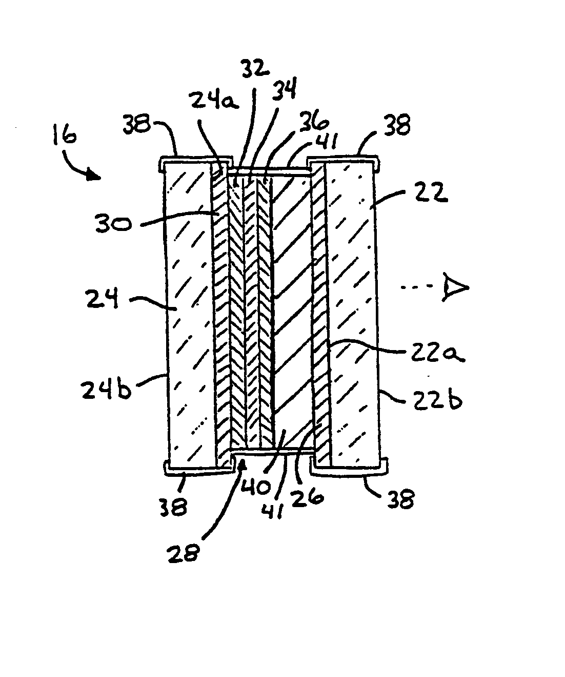
[0073]Referring now to the drawings and the illustrative embodiments depicted therein, an electrochromic interior rearview mirror assembly 10 is mounted to a mounting button 12 mounted at an interior surface of a windshield 14 of a vehicle (FIG. 2). Mirror assembly 10 includes a housing or casing 15 and an electrochromic reflective element or mirror element or cell 16 which has electrically variable reflectivity. Reflective element 16 includes first and second glass substrates 22, 24, and provides a third surface reflective element, whereby the reflective coating of the reflective element 16 is deposited on the third surface 24a of the substrates (FIG. 3). An electrochromic medium 40 and a plurality of metallic and non-metallic conductive or semi-conductive layers 28 are disposed between the electrochromic medium 40 and the second substrate 24. The refractive indices and physical thicknesses of the layers are selected to maximize transmission of a particular spectral band of light w...


PUM

PropertyMeasurementUnit
photopic reflectanceaaaaaaaaaa

Abstract

A mirror assembly for a vehicle includes a mirror element having at least one substrate that has a forward surface and a rearward surface. The mirror element comprises at least one substantially reflective metallic layer sandwiched between a respective pair of substantially transparent non-metallic layers. Each of the substantially transparent non-metallic layers and the substantially reflective metallic layer have a selected refractive index and a selected physical thickness such that the reflective element is selectively spectrally tuned to substantially transmit at least one preselected spectral band of radiant energy therethrough while substantially reflecting other radiant energy. A radiant energy emitting element is disposed at or near the rearward surface of the at least one substrate. The radiant energy emitting element is configured to emit radiant energy with a peak intensity within the at least one preselected spectral band.

Description

CROSS REFERENCE TO RELATED APPLICATIONS[0001]The present application is a 371 application of PCT Application No. PCT / US2003 / 029776, filed Sep. 19, 2003, which claims priority of U.S. provisional applications, Ser. No. 60 / 412,275, filed Sep. 20, 2002 by McCabe for ELECTROCHROMIC MIRROR ASSEMBLY; Ser. No. 60 / 424,116, filed Nov. 5, 2002 by McCabe for ELECTROCHROMIC MIRROR ASSEMBLY; and Ser. No. 60 / 489,816, filed Jul. 24, 2003 by McCabe for ELECTROCHROMIC MIRROR ASSEMBLY, which are all hereby incorporated herein by reference in their entireties.FIELD OF THE INVENTION[0002]The present invention relates to a mirror reflective element assembly for a vehicle, such as an electro-optic mirror reflective element assembly, such as an electrochromic interior or exterior rearview mirror reflective element assembly, and, more particularly, to a rearview mirror reflective element assembly which provides transmission of display information or illumination or radiant energy through the reflective ele...

Claims


Application Information

Patent Timeline
Patent Type & Authority Patents(United States)
IPC IPC(8): G02F1/15B60RG02B5/08G02B5/12G02B5/26G02B27/14
CPCB60R1/12G02B5/0858G02F1/157B60R2001/1215
Inventor MCCABE, IAN A.HABIBI, HAMIDVARAPRASAD, DESARAJU V.LYNAM, NIALL R.
Owner DONNELLY CORP
Why Eureka
Try Eureka