Magnetic resonance imaging having patient video, microphone and motion tracking

a technology of magnetic resonance imaging and patient video, applied in the field of magnetic resonance imaging having patient video, microphone and motion tracking, can solve the problem of not being able to monitor the movement, and achieve the effects of preserving the quality of the image, improving dynamic display, and fast (microsecond rise time) display

Active Publication Date: 2012-07-03
PITTSBURGH UNIV OF +1
View PDF30 Cites 38 Cited by
  • Summary
  • Abstract
  • Description
  • Claims
  • Application Information

AI Technical Summary

Benefits of technology

[0015]At least some of the above stated objects are achieved with an MRI device according to the present invention. The MRI device or system according to the present invention includes three MRI systems (or sub-systems), namely an MRI digital video projection system, an MRI motion tracker and patient augmented visual feedback system, and an MRI forward predictive noise canceling microphone system. The first system is an MRI Digital Video Projection System which uses a combination of digital video and digital components to provide high speed, precise digital video in an MRI magnet without introducing any RF noise. The second system is an MRI Motion Tracker and Patient Augmented Visual Feedback System that enables monitoring patient head motion (or any body part motion) and providing real time feedback to the patient and / or technician or technologist to minimize patient movement. The third system is an MRI Forward Predictive Noise Canceling Microphone system which provides a system and method that effectively removes the intense MRI acoustic noise produced during scanning by the magnet through the use of predicting the repeating signal of the MRI magnet (i.e. the noise) and canceling that acoustic noise signal leaving essentially only the patient's speech. The purpose of this invention is to solve critical needs for MRI patient communication / comfort, movement control, and speech communication. This will increase the diagnostic quality of the imaging (e.g., by reducing movement and better task control of brain activation), patient comfort (by providing distraction), and patient safety (making low volume speech understandable during the scan).
[0016]The MRI Digital Video Projection System involves providing digital video from a computer or digital video source projected into the magnet system. The present invention is an all digital solution including using the Digital Video Interface (DVI) from a computer or video device, a fiber optic DVI to fiber optic converter, a digital fiber optic cable, an optical to DVI converter, a Digital Light Processing (DLP) projector, specialty lenses to project the DVI image, and RF shielding and power signal filtering to limit the DLP projector EMF signals from interfering with the magnet or the magnet interfering with the DLP projector. Additionally, there is a screen viewable by the MRI patient, such as a rear projection screen, onto which the image may be projected. A prism or mirrors may be provided as needed to enable the patient to see the projected image. This system has the advantages of: being all digital and thereby preserving the quality of the image; using fiber optic transmission of signals thereby eliminating the potential of the cable bringing in or emitting radio signals that would distort the imaging process; using digital high speed DLP technology to enable very fast (microsecond rise time) displays showing better dynamic displays and enabling precise stimulation of the patient for brain mapping.
[0017]The MRI Motion Tracker and Patient Augmented Feedback System according to the present invention precisely monitors body part motion in an MRI environment, operates in the confined space of the magnet, and is not effected by and does not effect the MRI scanning operation, neither magnetically, electrically, or mechanically. This system involves monitoring body part movement and projecting that movement in up to six degrees of freedom (X, Y, Z, yaw, pitch, roll), or some reduced degrees of freedom, visually, and / or audibly, back to the patient and / or to the technician (or operator or technologist) to aid the patient in understanding and reducing movement. A typical example of use of this system would be monitoring head motion of an MRI patient during brain imaging. A significant part of this system is the use of an augmented virtual display projected to the patient and / or technologist during the scanning session to provide control and highlighting of the feedback to the patient (directly or via the technologist) to reduce movement. The visual feedback can optionally be enhanced with, or possibly replaced by, corresponding auditory feedback. For example, at the beginning of an MRI run there would be a display showing movement of the patient body part relative to the desired location. The patient would be given instruction on how to move the body part to return it to the desired location. During a scanning run the patient could be provided the movement displays to help them minimize movement. In some scanning, such as functional MRI scanning (fMRI), the patient must perform some task during the scanning and may not be able to monitor the movement during the run. In those cases the augmented display of movement can be discontinued for the patient (but provided to the technologist running the scan), or equivalent auditory feedback could be provided. At the end of the run the patient and technologist can review the movement track to help the patient understand and minimize future undesired movement. The display to the patient and technologist could be via a computer display showing graphically the movement, distance from the desired position of the body part, and position indicators for the body part (e.g., display of traffic light signal of green (good part location), yellow (warning) and red (bad) movement behavior).

Problems solved by technology

In some scanning, such as functional MRI scanning (fMRI), the patient must perform some task during the scanning and may not be able to monitor the movement during the run.

Method used


Image

  • Magnetic resonance imaging having patient video, microphone and motion tracking
  • Magnetic resonance imaging having patient video, microphone and motion tracking
  • Magnetic resonance imaging having patient video, microphone and motion tracking

Examples


Embodiment Construction

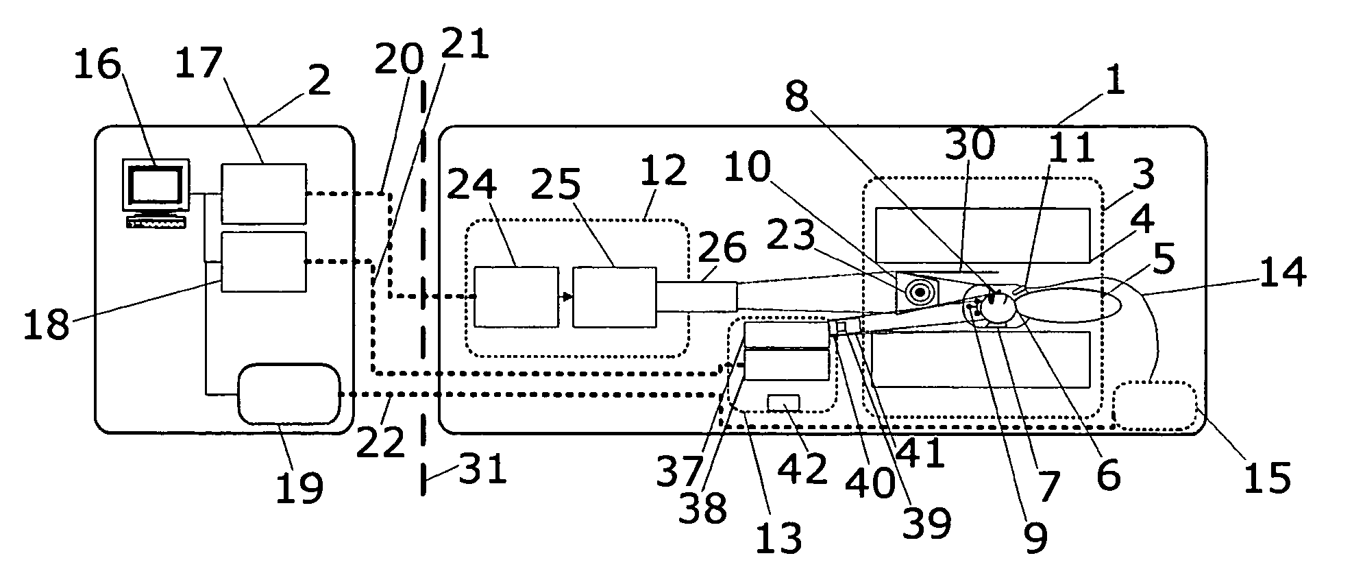
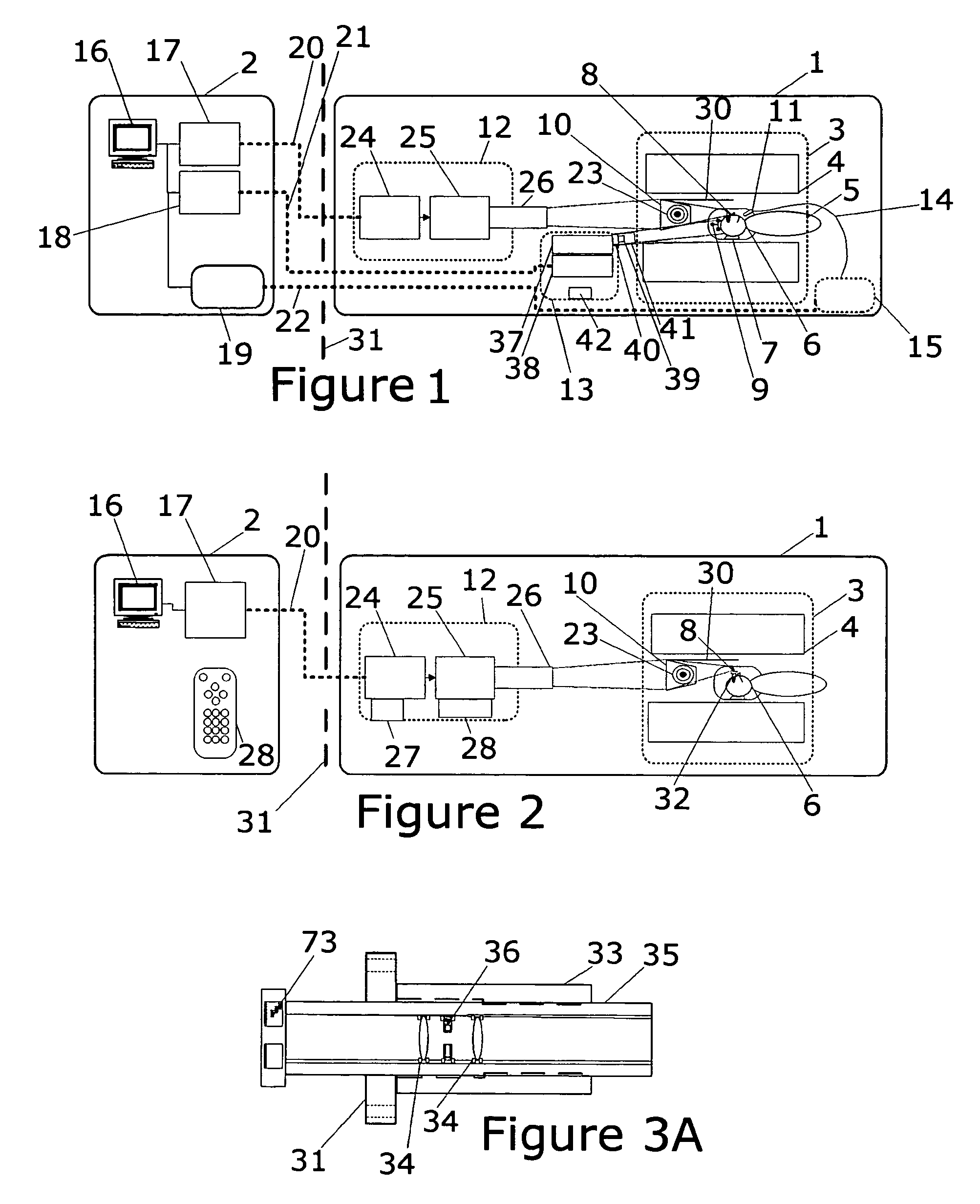
[0038]Reference will now be made in detail to the preferred embodiment of the invention. FIG. 1 provides to overview of all the components of the MRI system according to the present invention. The three sub-systems of the MRI system according to the present invention include a digital projection system, a movement monitoring system, and a microphone system can be used together, in other in combinations or individually. The equipment involves conventional components in the MRI magnet room 1 and the MRI control room 2, which components need not be discussed in detail herein. All signals pass through digital fiber optic cables (20, 21 and 22) through a penetration panel or wave guide 31.

[0039]The MRI Digital Video Projection System of the present invention is shown in FIG. 1-5. The system includes a viewable rear projection screen 23 that a patient can see typically by viewing it after the image is reflected from a mirror or prism 8. Other projection surfaces (e.g. front projection scr...


PUM


Abstract

Critical needs for MRI patient instruction, testing, comfort, motion control, and speech communication are provided for better imaging which leads to more effective medical care. An MRI Digital Video Projection System is disclosed which provides better quality display to the patient to better inform, instruct, test, and comfort the patient plus the potential to stimulate the brain with microsecond onset times to better diagnose brain function. An MRI Motion Tracker and Patient Augmented Visual Feedback System enables monitoring patient body part motion, providing real time feedback to the patient and / or technician to substantially improve diagnostic yield of scanning sessions, particularly for children and mentally challenged individuals. An MR Forward Predictive Noise Canceling Microphone System removes the intense MRI acoustic noise improving patient communication, patient safety and enabling coding of speech output. These systems can be used individually but maximum benefit is from providing all three.

Description

RELATED APPLICATION[0001]This application claims the benefit of U.S. provisional patent application Ser. No. 60 / 580,513 entitled “Patient Video Feed, Patient Microphone and Patient Motion Tracking in MRI” filed Jun. 17, 2004.BACKGROUND OF THE INVENTION[0002]1. Field of the Invention[0003]This invention relates to products used in MRI imaging, specifically providing systems to provide high speed digital video images to the MRI system patient, collect speech data from the MRI system patient and to track and to minimize patient movement within the MRI system. These systems enhance patient cooperation to improve the quality of scanner data collection. The innovations of the present invention will enhance diagnostic effectiveness of MRI imaging, patient comfort, patient safety, and will lower MRI imaging costs.[0004]2. Background Information[0005]Magnetic Resonance Imaging (MRI) allows research and diagnostic imaging of humans and animals. An MRI provides two and three dimensional imagin...

Claims


Application Information

Patent Timeline
Patent Type & Authority Patents(United States)
IPC IPC(8): A61B5/05A61B5/055A61B5/11G01R33/28
CPCA61B5/0555G01R33/283A61B5/11A61B5/055
Inventor ZUCCOLOTTO, ANTHONY P.SCHNEIDER, WALTERBASLER, LEROY K.
Owner PITTSBURGH UNIV OF
Why Eureka
Try Eureka