Turbomachine rotor blade

a technology of rotor blades and turbines, which is applied in the direction of liquid fuel engines, vessel construction, marine propulsion, etc., can solve the problems of increasing the risk of contact between the blade tips and the inside walls of the casing, reducing the radial clearance, and reducing the risk of dynamic self-engagement. , to achieve the effect of reducing the risk of dynamic self-engagemen

Active Publication Date: 2015-04-30
SN DETUDE & DE CONSTR DE MOTEURS DAVIATION S N E C M A
View PDF5 Cites 42 Cited by
  • Summary
  • Abstract
  • Description
  • Claims
  • Application Information

AI Technical Summary

Benefits of technology

[0008]The present invention seeks to further reduce the risk of dynamic self-engagement in a rotor blade comprising a back-swept d

Problems solved by technology

Nevertheless, this reduction in radial clearance gives rise to an increase in the risk of contact between the blade tips and the inside walls of the casing.
Such contact can be particularly dangerous if the frequency of contact enters into resonance with the resonant frequency of the blades in b

Method used


Image

  • Turbomachine rotor blade
  • Turbomachine rotor blade
  • Turbomachine rotor blade

Examples


Embodiment Construction

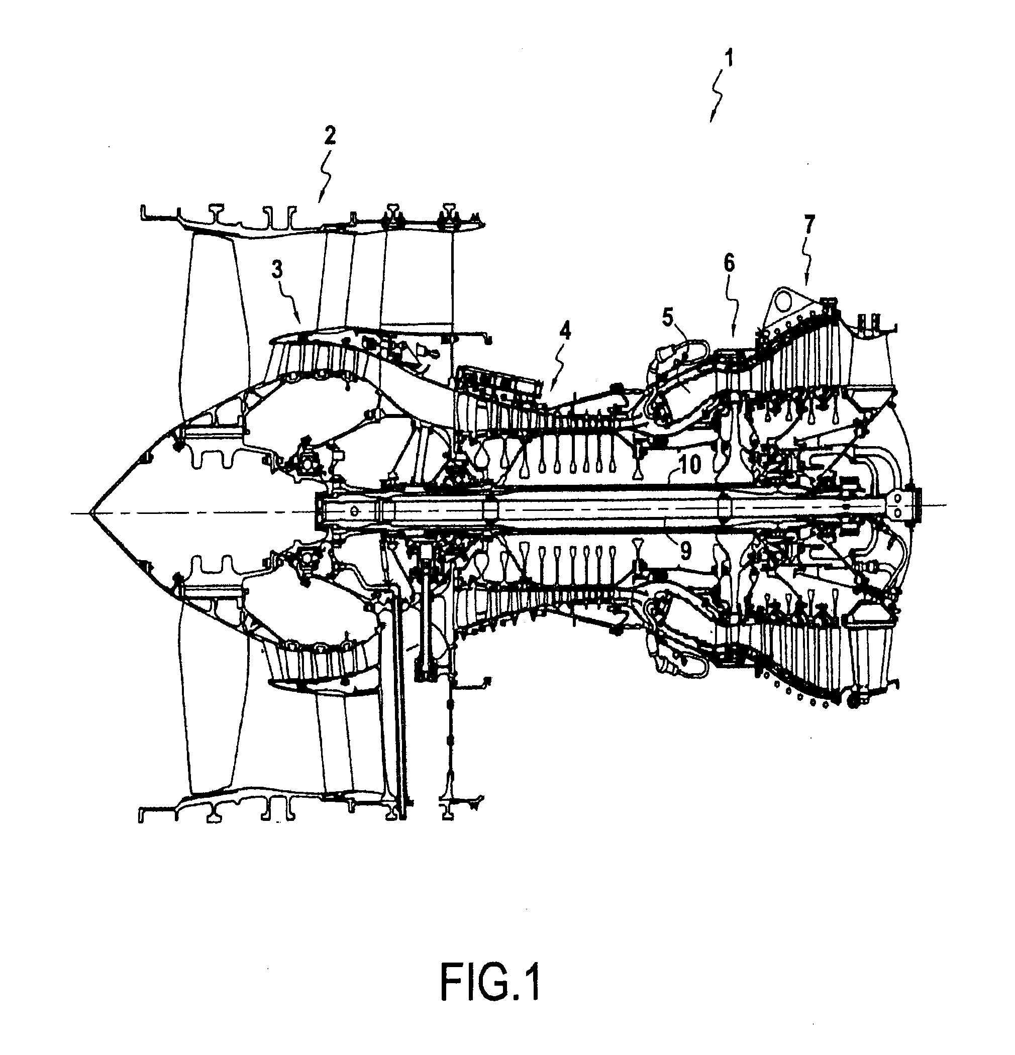
[0030]FIG. 1 shows an illustrative example of a turbomachine, and more specifically of an axial-flow turbofan 1. The turbofan 1 shown comprises a fan 2, a low pressure compressor 3, a high pressure compressor 4, a combustion chamber 5, a high pressure turbine 6, and a low pressure turbine 7. The fan 2 and the low pressure compressor 3 are connected to the low pressure turbine 7 by a first transmission shaft 9, while the high pressure compressor 4 and the high pressure turbine 6 are connected together by a second transmission shaft 10. In operation, a flow of air compressed by the low and high pressure compressors 3 and 4 feeds combustion in the combustion chamber 5, with expansion of the combustion gas driving the high and low pressure turbines 6 and 7. By means of the shafts 9 and 10, the turbines 6 and 7 thus drive the fan 2 and the compressors 3, 4. The air propelled by the fan 2 and the combustion gas leaving the turbojet 1 via a thrust nozzle (not shown) downstream from the tur...


PUM


Abstract

A turbomachine rotor blade including a blade root and a blade tip spaced apart by a blade height, including at least one intermediate segment between the blade root and the blade tip that presents forward sweep over at least 50% of the blade height, and a distal segment with backward sweep between the intermediate segment and the blade tip, the distal segment also presenting a positive tangential angle of inclination.

Description

BACKGROUND OF THE INVENTION[0001]The present invention relates to the field of turbomachine blades, and more particularly to the field of turbomachine rotor blades.[0002]In the present context, the term “turbomachine” is used to designate any machine in which energy can be transferred between a fluid flow and at least one set of blades, such as for example, a compressor, a pump, a turbine, or a combination of at least two of them. In the description below, the terms “upstream” and “downstream” are defined relative to the normal flow direction of the fluid through the turbomachine.[0003]Such a turbomachine may comprise a plurality of stages, each stage normally comprising two sets of airfoils, namely a set of movable blades and a set of stationary guide vanes. Such a set comprises a plurality of airfoils that are offset from one another in a lateral direction. Typically the airfoils are arranged radially around a central axis A. Thus, such a set forms a rotor when it constitutes a se...

Claims


Application Information

Patent Timeline
IPC IPC(8): F04D29/38F04D19/00F01D5/14
CPCF04D29/384F05D2250/38F04D19/002F01D5/141F01D5/14F05D2220/36F04D29/324Y02T50/60
Inventor PERROT, VINCENTCOINTE, JULIENRIOS, JEAN-FRANCOIS
Owner SN DETUDE & DE CONSTR DE MOTEURS DAVIATION S N E C M A
Why Eureka
Try Eureka