Pattern evaluation system, pattern evaluation method and program

Active Publication Date: 2007-09-25
KIOXIA CORP
View PDF16 Cites 6 Cited by
  • Summary
  • Abstract
  • Description
  • Claims
  • Application Information

AI Technical Summary

Benefits of technology

[0012]According to a third aspect of the present invention, there is provided a program which causes a computer to execute a pattern evaluation method comprising: acquiring an image data of a pattern to

Problems solved by technology

However, in the above described conventional method for detecting the edge points of the pattern, there are some cases where no edge can be detected or an incorrect edge is detected by mistake, in accordance with the shape and arrangement of the pattern.
Therefore, if the shape of the pattern is complicated, it is required to carry ou

Method used


Image

  • Pattern evaluation system, pattern evaluation method and program
  • Pattern evaluation system, pattern evaluation method and program
  • Pattern evaluation system, pattern evaluation method and program

Examples


first embodiment

[0037](1) First Embodiment

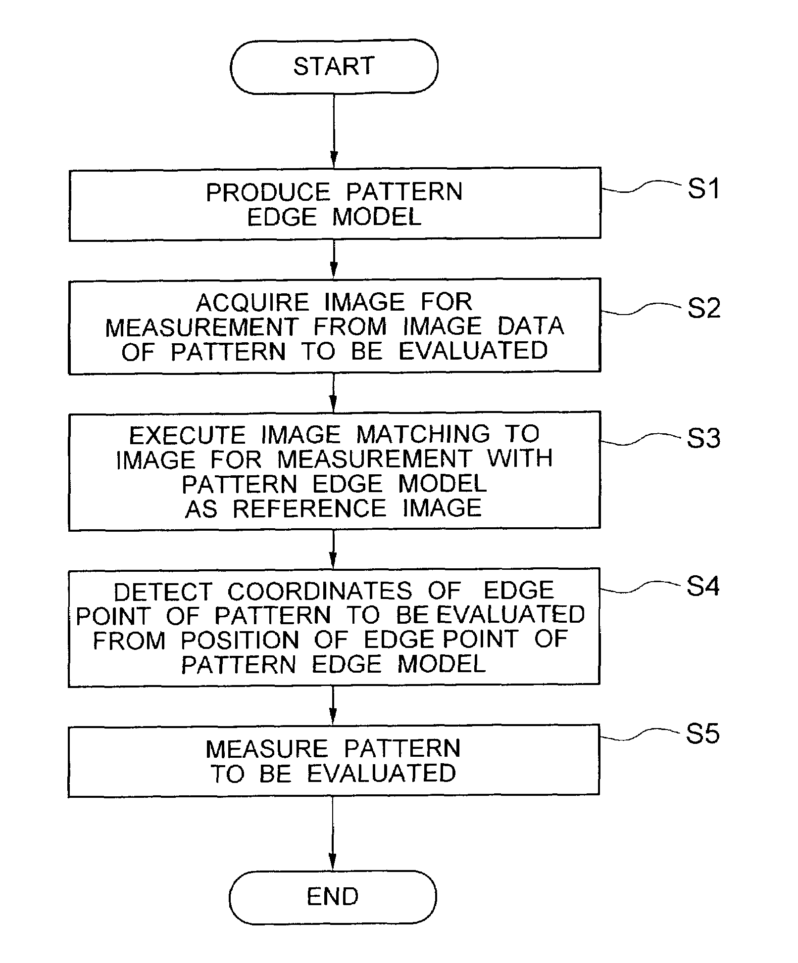
[0038]First, referring to FIGS. 2 through 10, the first embodiment of a pattern evaluation method according to the present invention will be described below. In this embodiment, the measurement of a line pattern will be described.

[0039]FIG. 2 is a flow chart for explaining a schematic procedure in this embodiment. As shown in this figure, prior to the detection of pattern edge points, a pattern edge model is previously produced (step S1). Examples of pattern edge models in this embodiment are shown in FIGS. 3A through 3C. Each of pattern edge models MT1 through MT3 shown in these figures are an array of pixels wherein intensity values of 8 bits are stored, and the position of each of edge points EP1 through EP3 is also defined in each model. Each of the edge points of the pattern edge model is herein defined as an edge point detected when the pattern to be evaluated is viewed from left to right. In fact, the pattern edge model is stored in the image memory ...

second embodiment

[0054](2) Second Embodiment

[0055]Referring to FIGS. 11A and 11B, the second embodiment of a pattern evaluation method according to the present invention will be described below. In this embodiment, the detection of an edge of a closed curve, such as a hole pattern, will be described.

[0056]As a pattern edge model, the same models as those described in the first embodiment are considered. In the case of a closed curve, edge points are distributed in all directions unlike the line pattern. For that reason, it is impossible to carry out the measurement while the scanning direction of a reference image is fixed in horizontal directions. Therefore, for example, as shown in FIG. 11A, it is possible to detect edge points in all directions by scanning a hole pattern P4 in the Y directions DS3 and DS4 in addition to X directions DS1 and DS2 with reference images each of which corresponds to Y directions DS3 and DS4, and to Y directions DS3 and DS4,respectively. As shown in FIG. 11B, similar t...

third embodiment

[0058](3) Third Embodiment

[0059]For a pattern edge model, the array of pixels, the intensity values stored therein, and the positions of the edge points must be defined prior to the detection of the edge points. These defined data comprise, e.g., matrix data, as shown in FIG. 7, and can be simply prepared and edited by the operation of a numerical value file. In this embodiment, however, there is provided a method for producing a pattern edge model from an actual image without operating such a numerical file.

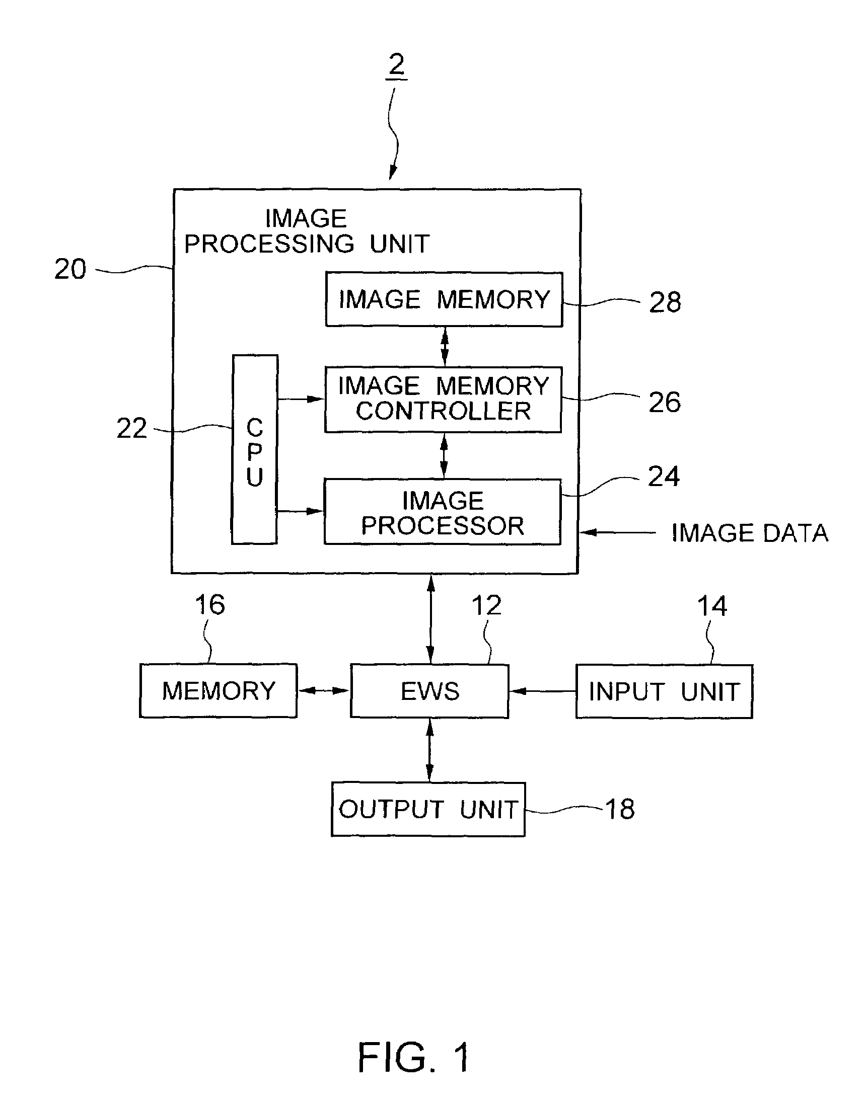
[0060]First, prior to the preparation of a pattern edge model, a range assigning window is used for assigning a portion of an image to be defined as an edge on an actual image displayed by the output unit 18 (see FIG. 1), by means of an appropriate input unit 14, e.g., a mouse. At this time, it is convenient to set the image processor 24 so that the assigned range is enlarged to be displayed on another window.

[0061]Then, the edge of the pattern is defined and displayed on the ac...


PUM


Abstract

a pattern evaluation system which receives image data of a pattern to be evaluated to evaluate the pattern includes an edge model producing part which produces a pattern edge model and an edge point coordinate detecting part which carries out an image matching processing to an image of the pattern with the pattern edge model to detect coordinates of an edge point of the pattern.

Description

CROSS REFERENCE TO RELATED APPLICATION[0001]This application claims benefit of priority under 35USC § 119 to Japanese patent application No. 2001-294209, filed on Sep. 26, 2001, the contents of which are incorporated by reference herein.BACKGROUND OF THE INVENTION[0002]1. Field of the Invention[0003]The present invention generally relates to a pattern evaluation system, evaluation method and program for evaluating a pattern by measuring dimension and shape of the pattern.[0004]2. Description of the Prior Art[0005]As an example of a conventional pattern evaluation method, a method for evaluating a fine pattern of a semiconductor will be described below.[0006]Evaluation of a pattern is important in a semiconductor fabricating process. This is particularly conspicuous with respect to a fine pattern formed in a lithography process and / or an etching process. Conventionally, there is generally adopted a method for measuring and evaluating the dimension of a pattern (e.g., a line width in ...

Claims


Application Information

Patent Timeline
IPC IPC(8): G06K9/48G06K9/00G06T5/00G06T7/00G06T7/60
CPCG06T7/0004G06T7/0083G06T7/602G06T2207/10056G06T2207/30148G06T7/12G06T7/62
Inventor MITSUI, TADASHI
Owner KIOXIA CORP
Why Eureka
Try Eureka