Heat-dissipating fan and its housing

a technology of heat dissipation fan and housing, which is applied in the direction of machines/engines, stators, liquid fuel engines, etc., can solve the problems of noisy noise, easy damage, and high heat generation of electronic devices during operation

Active Publication Date: 2007-10-02
DELTA ELECTRONICS INC
View PDF6 Cites 37 Cited by
  • Summary
  • Abstract
  • Description
  • Claims
  • Application Information

AI Technical Summary

Problems solved by technology

In a normal electronic product such as a computer, electronic devices will generate a lot of heat during operation.
If the electronic devices are continuously operated at high temperature, they are easily damaged.
Furthermore, the distance H between the lower edge of the blade 121 and the upper edge of the rib or stationary blade 13 is relatively small such that it will cause a lot of noise in a very short time as the airflow passes therethrough and worsen the sound, resulting from the air turbulence.

Method used


Image

  • Heat-dissipating fan and its housing
  • Heat-dissipating fan and its housing
  • Heat-dissipating fan and its housing

Examples


Embodiment Construction

[0031]The present invention will now be described more detailedly with reference to the following embodiments. It is to be noted that the following descriptions of the preferred embodiments of this invention are presented herein for the purpose of illustration and description only. It is not intended to be exhaustive or to be limited to the precise form disclosed.

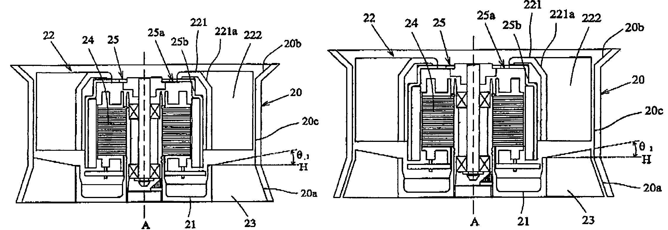
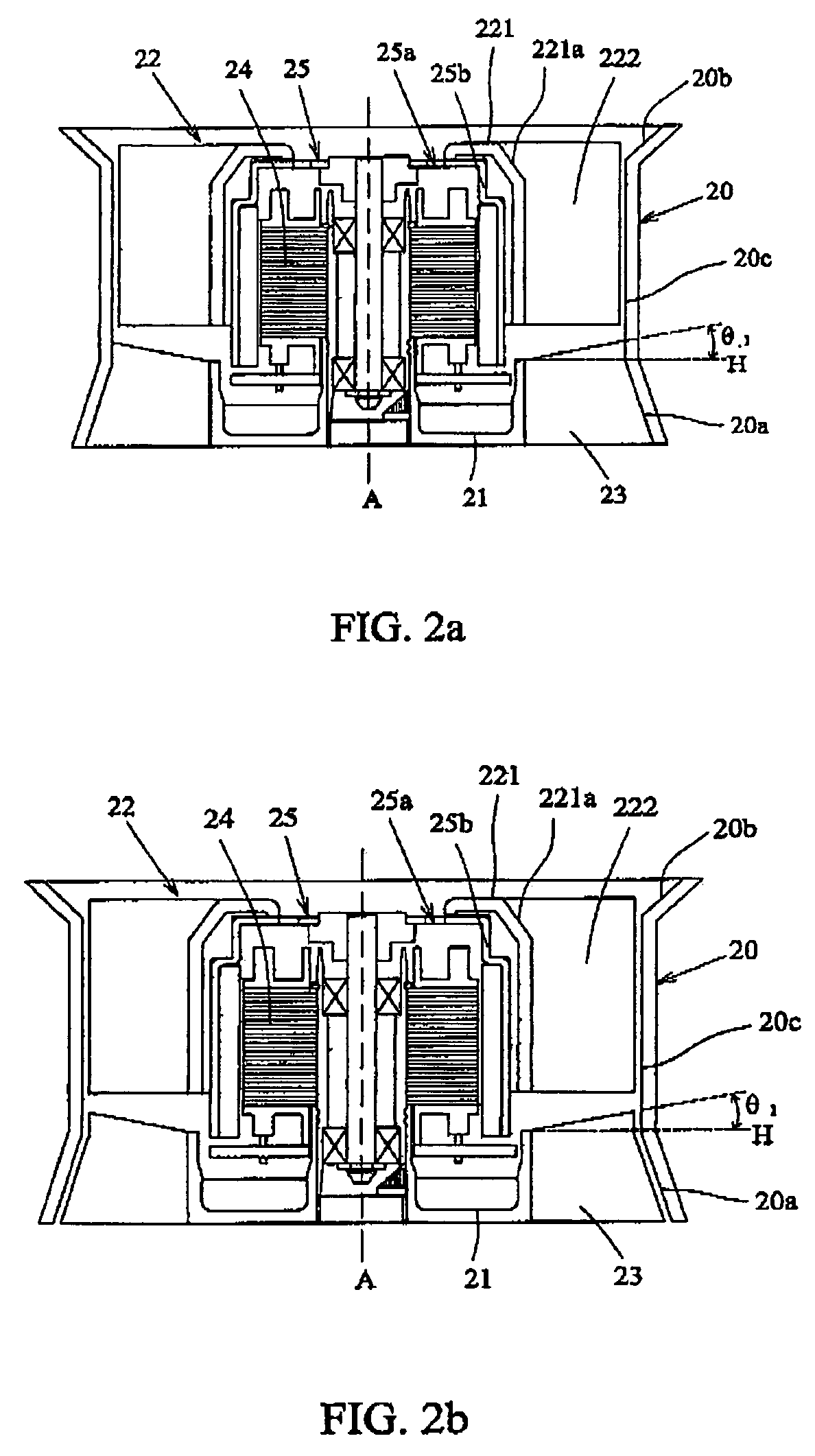
[0032]First of all, please refer to FIG. 2a which shows the first preferred embodiment of the heat-dissipating fan of the present invention. The heat-dissipating fan includes a housing 20, a base 21 mounted inside the housing 20 for supporting a driving device or motor 24 used for driving the heat-dissipating fan to rotate, and an air-guiding member 23 disposed between the base 21 and the housing 20 and positioned at the air outlet side or the air inlet side of the heat-dissipating fan.

[0033]The heat-dissipating fan further includes an impeller 22 having a hub 221 and a plurality of blades 222 arranged around the hub 221. T...


PUM


Abstract

A heat-dissipating fan with an upward air-guiding member is provided. The heat-dissipating fan includes a housing, an impeller having a hub and a plurality of blades disposed around the hub, a base disposed inside the housing for supporting the impeller thereon, and an air-guiding member disposed between the base and the housing, wherein the air-guiding member has at least one inclined edge on the windward side or its opposite side relative to the horizontal line perpendicular to the axis of the heat-dissipating fan.

Description

FIELD OF THE INVENTION[0001]The present invention is related to a heat-dissipating fan and its housing, and especially to an axial-flow fan and its housing.BACKGROUND OF THE INVENTION[0002]In a normal electronic product such as a computer, electronic devices will generate a lot of heat during operation. If the electronic devices are continuously operated at high temperature, they are easily damaged. Thus, to prevent such a damage, a heat-dissipating fan is normally disposed in the electronic product to dissipate heat to the surrounding.[0003]Please refer to FIG. 1 which shows a conventional axial-flow fan for the computer. The conventional axial-flow fan mainly includes a housing 10, a motor 11 and an impeller 12 with a plurality of blades. The housing 10 includes a base 14 for supporting the motor 11 and has a plurality of ribs or stationary blades 13 at the air outlet side of the axial-flow fan. When the motor 11 drives the impeller 12 to rotate, the blades 121 will dischage the a...

Claims


Application Information

Patent Timeline
Patent Type & Authority Patents(United States)
IPC IPC(8): F04D29/52F04D29/66
CPCF04D25/0613F04D29/542Y10S415/915F04D29/544
Inventor LEE, CHIN-HUNGCHANG, SHUN-CHENLIN, KUO-CHENGHUANG, WEN-SHICHANG, HSIOU-CHEN
Owner DELTA ELECTRONICS INC
Why Eureka
Try Eureka