Electrical service monitoring system

a technology of service monitoring and monitoring system, which is applied in the direction of power distribution line transmission, powerline communication applications, instruments, etc., can solve the problems of electrical costs that cannot be monitored, the rate of power usage during any given time is typically unavailable,

Inactive Publication Date: 2007-10-02
SPRINT CORPORATION
View PDF6 Cites 93 Cited by
  • Summary
  • Abstract
  • Description
  • Claims
  • Application Information

AI Technical Summary

Problems solved by technology

The rate of power usage during any given time is typically unavailable.
A consumer that wishe

Method used


Image

  • Electrical service monitoring system
  • Electrical service monitoring system
  • Electrical service monitoring system

Examples


Embodiment Construction

[0013]FIGS. 1-2 and the following description depict specific examples to teach those skilled in the art how to make and use the best mode of the invention. For the purpose of teaching inventive principles, some conventional aspects have been simplified or omitted. Those skilled in the art will appreciate variations from these examples that fall within the scope of the invention. Those skilled in the art will appreciate that the features described below can be combined in various ways to form multiple variations of the invention. As a result, the invention is not limited to the specific examples described below, but only by the claims and their equivalents.

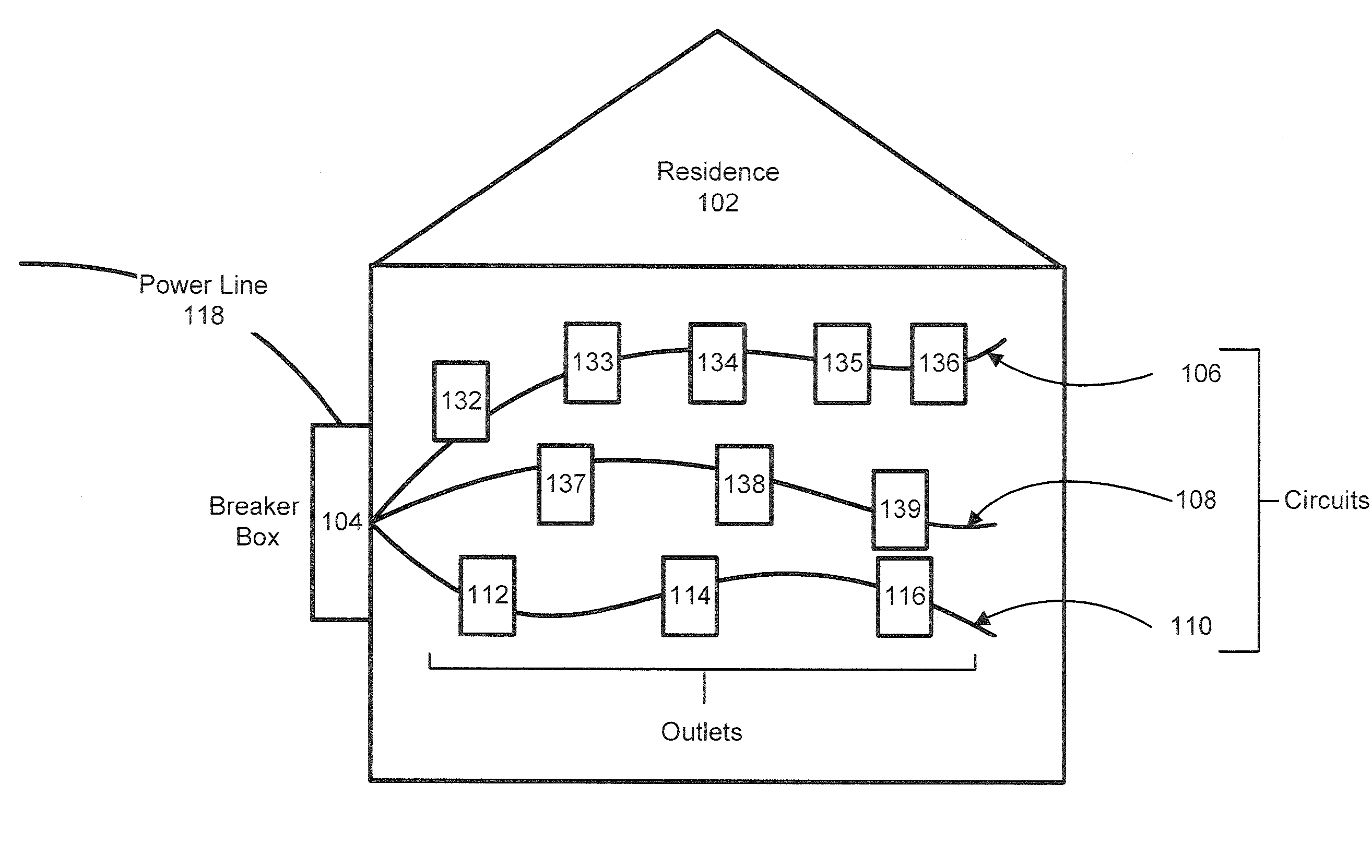
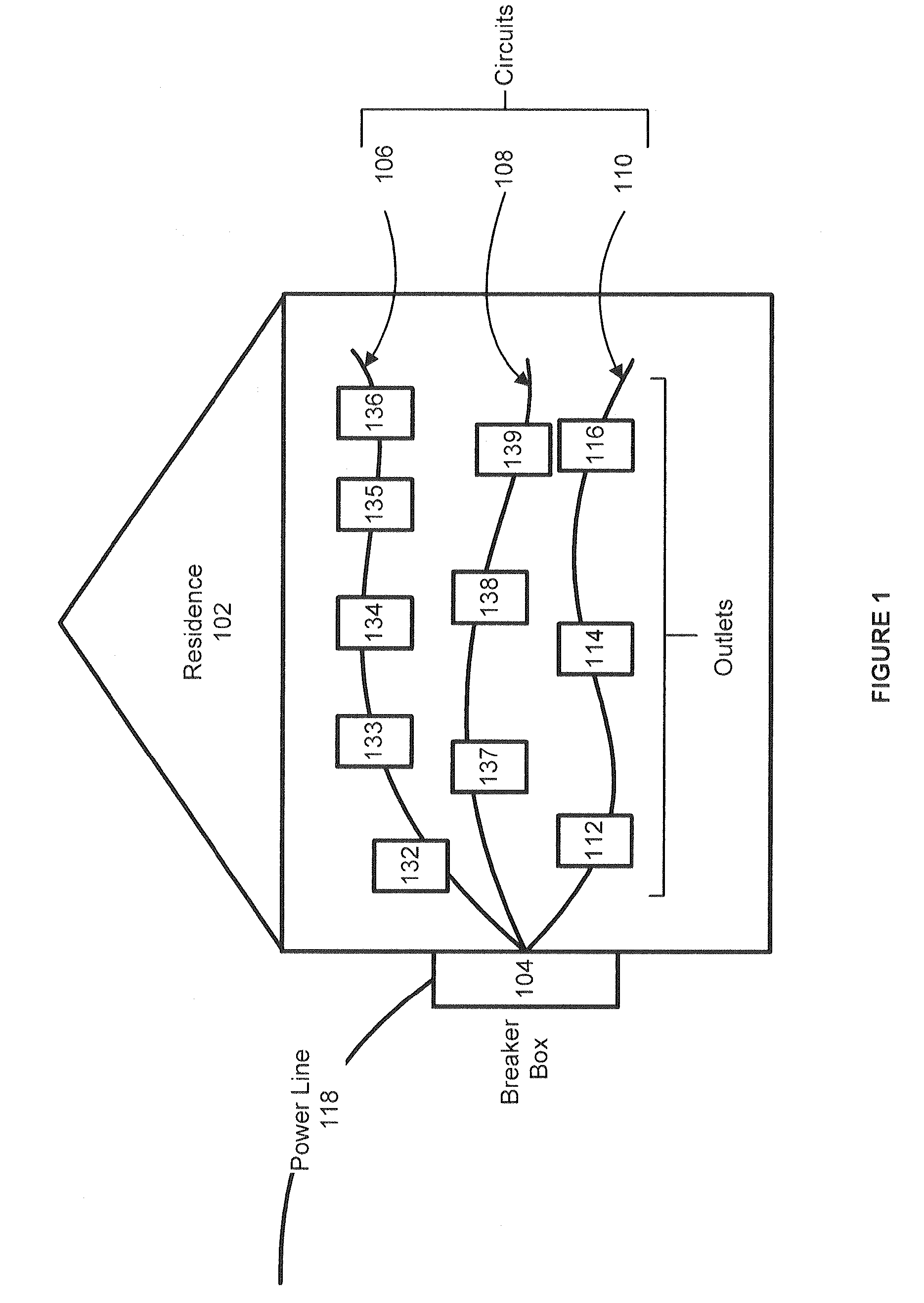
[0014]FIG. 1 is a schematic view of the electrical system in a residence in an example embodiment of the current invention. Residence 102 is fed by incoming power line 118. Power line 118 terminates into breaker box 104. A plurality of circuits are connected to breaker box 104. For clarity, only three circuits, 106, 108, and 110, ...


PUM


Abstract

A system and method that allows a consumer to monitor the electrical power usage in a residence is disclosed. The electrical use may be monitored at the service level, the circuit level, or at the group level. The electrical usage is communicated to a power monitoring system using a power line communications network (PLC). The monitored electrical usage can be accessed by both the utility supplying the electricity and by the consumer or owner of the residence.

Description

RELATED APPLICATIONS[0001]Not applicableFEDERALLY SPONSORED RESEARCH OR DEVELOPMENT[0002]Not applicableMICROFICHE APPENDIX[0003]Not applicableBACKGROUND OF THE INVENTION[0004]1. Field of the Invention[0005]The invention is related to the field of electrical distribution systems, and in particular, to monitoring the electrical use of a residence using the electrical wires as part of the communications network.[0006]2. Description of the Prior Art[0007]Typically, the electrical power used by a residence is monitored with an external meter. The meter is checked once a month to determine the amount of electrical power used by the residence. Many meters are manually checked, although remotely read meters are gaining prevalence. In most cases the amount of power used by the residence is accumulated over the month and only the total amount of power used during the month is recorded. The rate of power usage during any given time is typically unavailable. Utilities typically charge more for ...

Claims


Application Information

Patent Timeline
IPC IPC(8): G01R11/63H04B3/54
CPCG01R22/10H04B3/54H04B2203/5458H04B2203/5433
Inventor EULER, TIMOTHY D.JOHNSON, HAROLD W.
Owner SPRINT CORPORATION
Why Eureka
Try Eureka