Restricting device

a technology of restricting devices and vents, which is applied in the direction of door/window fittings, multi-purpose tools, construction, etc., can solve the problems of not being able to add to restrict the movement of a vent that is already in place, complicated devices to manufacture, and difficult to use, etc., to achieve the effect of simple and easy operation

Active Publication Date: 2007-10-09
ASSA ABLOY LTD
View PDF27 Cites 9 Cited by
  • Summary
  • Abstract
  • Description
  • Claims
  • Application Information

AI Technical Summary

Benefits of technology

[0004]The present invention aims to provide a restricting device that is simple and easy to operate. The restricting device provided

Problems solved by technology

Although a number of restricting devices have been suggested in the prior art, many of such devices are complicated to manufacture and difficult to use.
In particular, many of

Method used


Image

  • Restricting device
  • Restricting device
  • Restricting device

Examples


Embodiment Construction

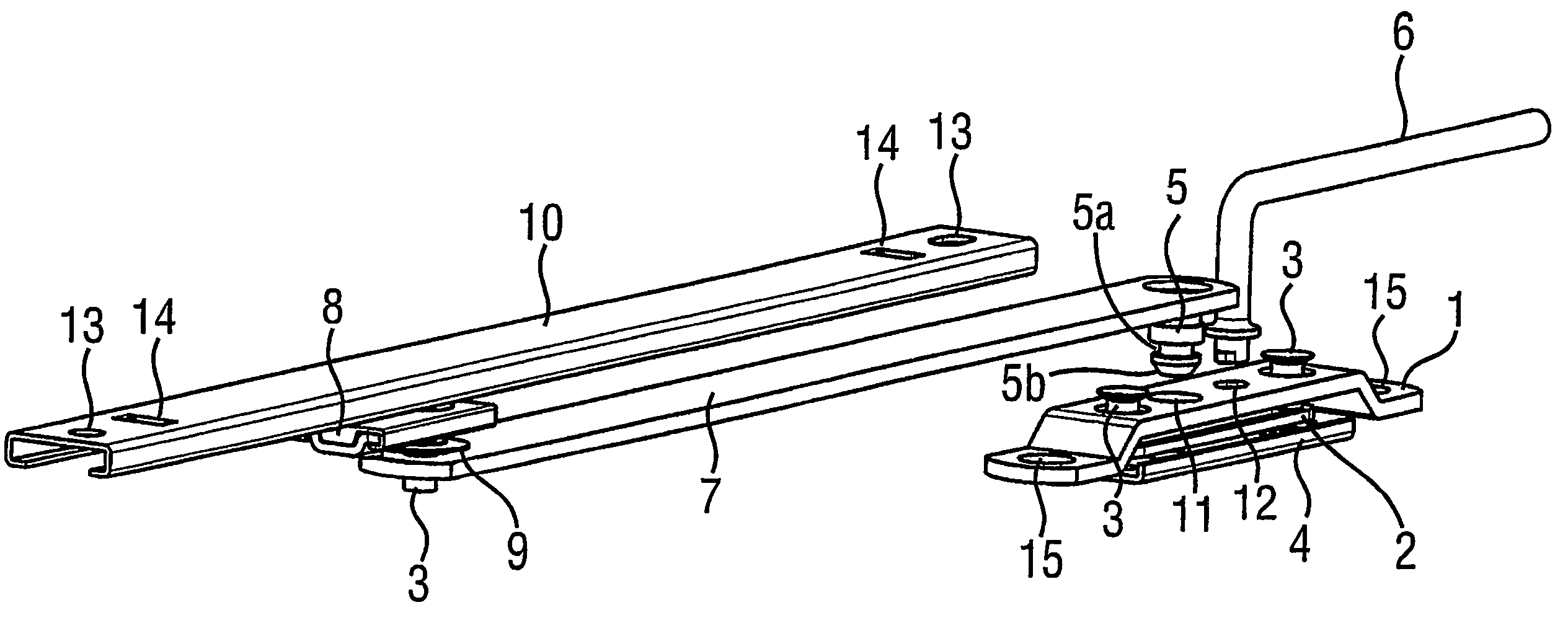
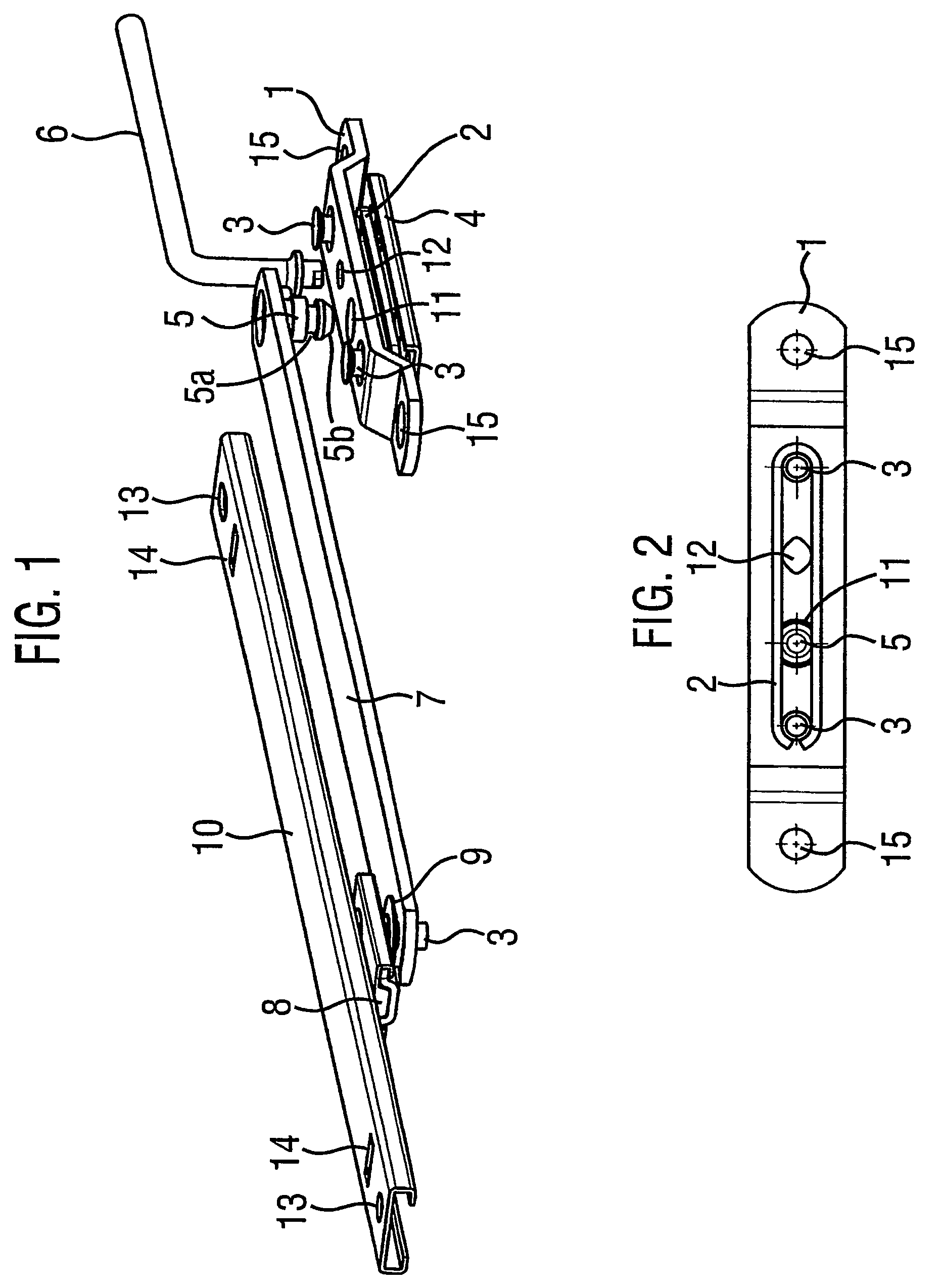
[0024]Referring to FIG. 1, a restricting device comprises a joggled link (or mounting plate) 1 for attachment to a frame (not shown), a C-section track 10 for attachment to a vent (not shown), a slider 8, a pivot arm 7, a locking pin 5, a spring 2, and a key 6.

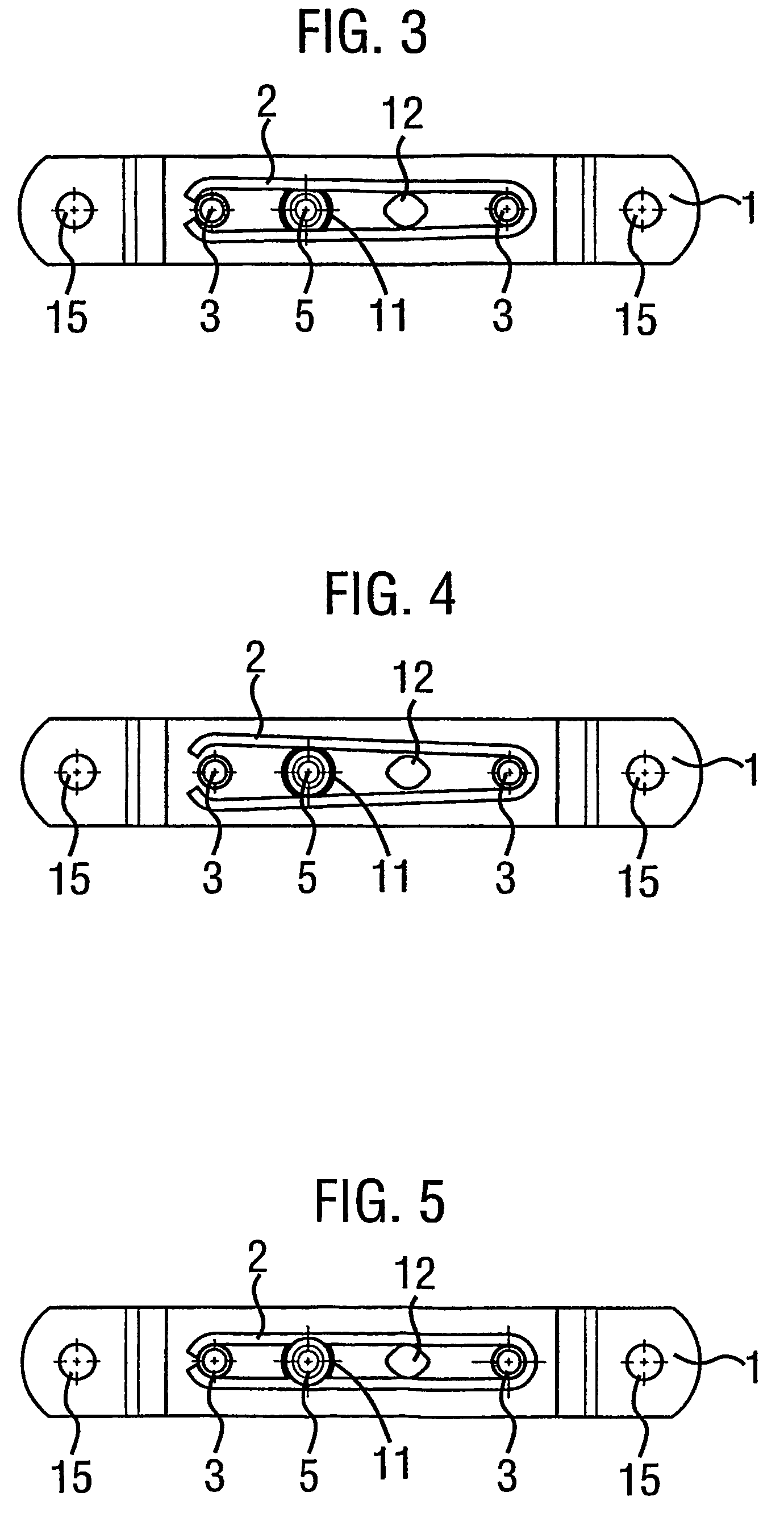
[0025]The joggled link includes screw-holes 15 to facilitate the attachment of the joggled link to the frame. The spring 2 is located beneath the joggled link 1 and above a support plate 4. The spring comprises a resilient strip of metal having two legs. Rivets 3 hold the joggled link 1, spring 2 and support plate 4 together. The rivets 3 also hold the two legs of the resilient strip of metal in an operative position to enable engagement with a locking pin on the arm to occur.

[0026]The track 10 includes screw-holes 13 to facilitate attachment of the track to a vent. A slider 8 is engaged with the track 10 such that it can slide along it. The track 10 also includes crack stops 14 which limit the extent to which the slider 8 can...


PUM


Abstract

The invention provides a restricting device for a closure including a vent hingedly connected to a frame, the restricting device comprising a plate (1,4) for mounting on a frame, an arm (7) for pivotally mounting on a vent and means for releasably interengaging the arm and the plate, wherein, in use, when the plate and the arm are interengaged, the closure can only be opened a predetermined distance. The means for releasably interengaging the arm and the plate comprise a resilient means (2) adapted to engage a locking pin (5). The engagement between the arm and the plate is released by means of a release means, for example a key (6,6′;6″), which is separate from the rest of the device. A preferred embodiment of the invention provides means (16,17; 18, 20) for preventing over-rotation of the key beyond a position in which the resilient means is in an optimum release position. The device is simple to use and has the advantage that it is detachable.

Description

FIELD OF THE INVENTION[0001]The present invention relates to restricting devices, and in particular to releasable restricting devices that limit the opening and closing of a vent.BACKGROUND OF THE INVENTION[0002]Windows often include a vent connected to a frame by a hinge. This arrangement enables the window to be opened widely. However, it is often desirable to be able to restrict the extent to which this type of window can be opened during normal use for reasons of safety and security. Any device for restricting the opening of a window during normal use must also allow the window to be opened fully when required, for example for cleaning or in the case of a fire.[0003]Although a number of restricting devices have been suggested in the prior art, many of such devices are complicated to manufacture and difficult to use. In particular, many of the prior art restricting devices have to be incorporated when a vent is manufactured or hung, and cannot be added to restrict the movement of...

Claims


Application Information

Patent Timeline
IPC IPC(8): E05D3/06E05C17/04E05C17/24
CPCE05C17/045E05C17/24Y10T16/5357Y10T16/547Y10T16/53607
Inventor SMITH, MATHEW JOHN
Owner ASSA ABLOY LTD
Why Eureka
Try Eureka