Submarine

a technology of submersibles and submerged bodies, applied in underwater equipment, weapons, offensive equipment, etc., can solve the problems of high destruction force, unfavorable flow resistance, sophisticated and expensive, etc., and achieve the effect of low cost and comparatively inexpensive availability on the mark

Active Publication Date: 2007-10-09
THYSSENKRUPP MARINE SYST GMBH +1
View PDF14 Cites 2 Cited by
  • Summary
  • Abstract
  • Description
  • Claims
  • Application Information

AI Technical Summary

Benefits of technology

[0011]The basic concept of the present invention is to equip the submarine with a gun, but however to arranged this gun on an extending apparatus in order in this manner to also be able to combat on sea, land or in the air in a targeted manner. Since a recoil is produced with conventional guns having a projectile size range of about 10 to 40 mm diameter of interest here, and this recoil, given a required extended height of five meters for example, would demand an extremely extensive design of the extending apparatus in order to accommodate the recoil, i.e. in order to transmit the force via the extending apparatus to the submarine in a manner such that the weapon remains directed on the target, according to the invention, an essentially recoil-free gun is provided. Moreover, according to the invention, a container resistant to the underwater pressure is provided in which the weapon lies protected from external influences, in particular seawater, during submerged travel. By way of this it is possible to apply a modern recoil-free gun as has typically been developed for application on land and is available comparatively inexpensively on the market. On account of the solution according to the invention, it thus becomes possible to provide additional weaponry for the submarine which is highly effective for the previously mentioned tasks, at a relatively low cost, and which may be used without the submarine having to surface.

Problems solved by technology

This weapon may however only be applied in the surfaced condition, and in the submerged condition produces an unfavorable flow resistance, and is furthermore complicated with regard to its design since all components of the weapon must be resistant to sea water and must be deigned in pressure-resistant manner.
Disregarding the fact that the submarine must always be brought into the semi-submerged condition for this purpose, the missile launcher has the disadvantage that on the one hand the weapons launched with this have a very high destruction force and on the other hand are very sophisticated and expensive so that it is not suitable for tactical purposes such as for stopping commercial ships or for seizing pirate ships.
Here it is the case of missiles and torpedoes which create extreme damage to the targets if they don't completely destroy these.

Method used


Image

  • Submarine
  • Submarine
  • Submarine

Examples


Embodiment Construction

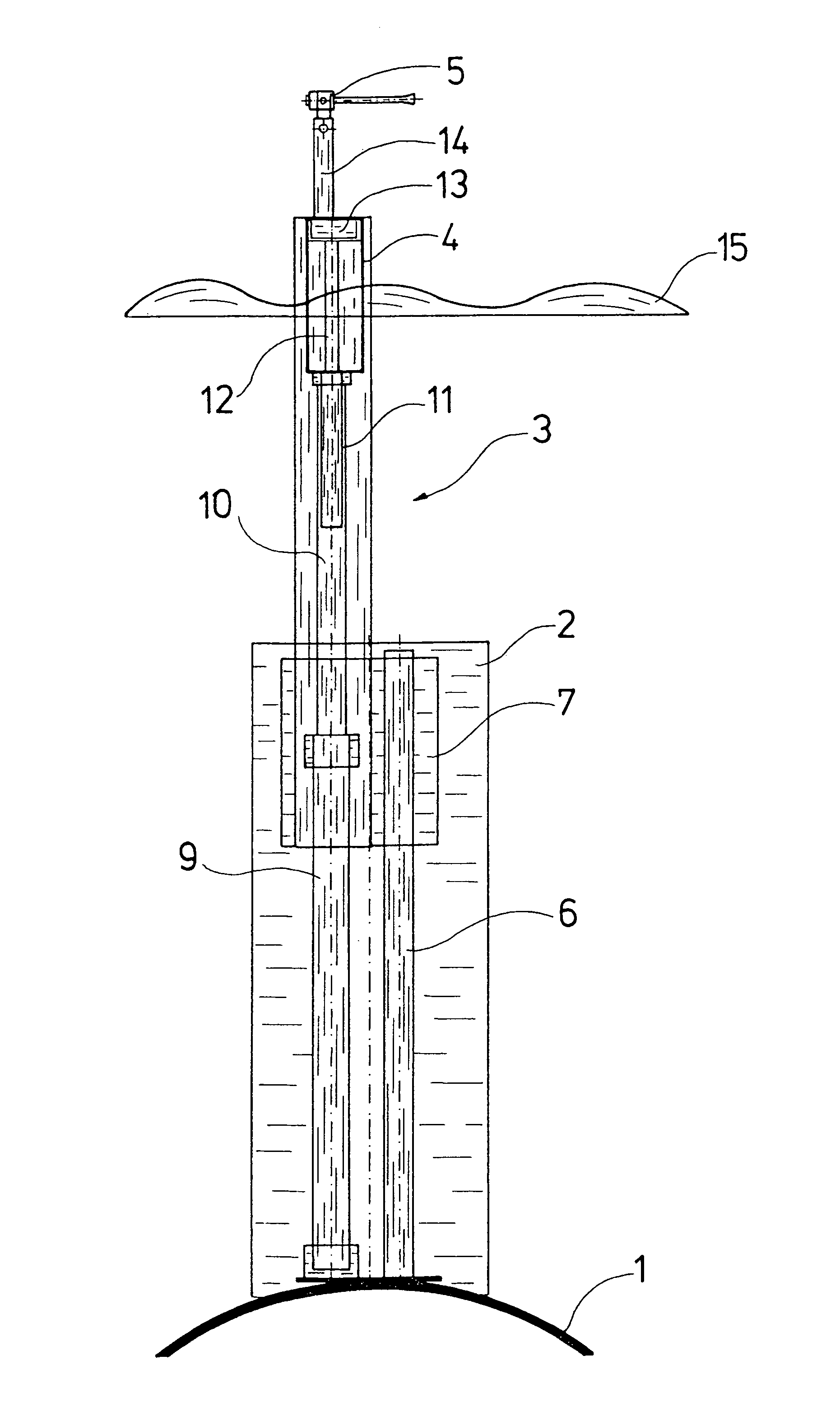
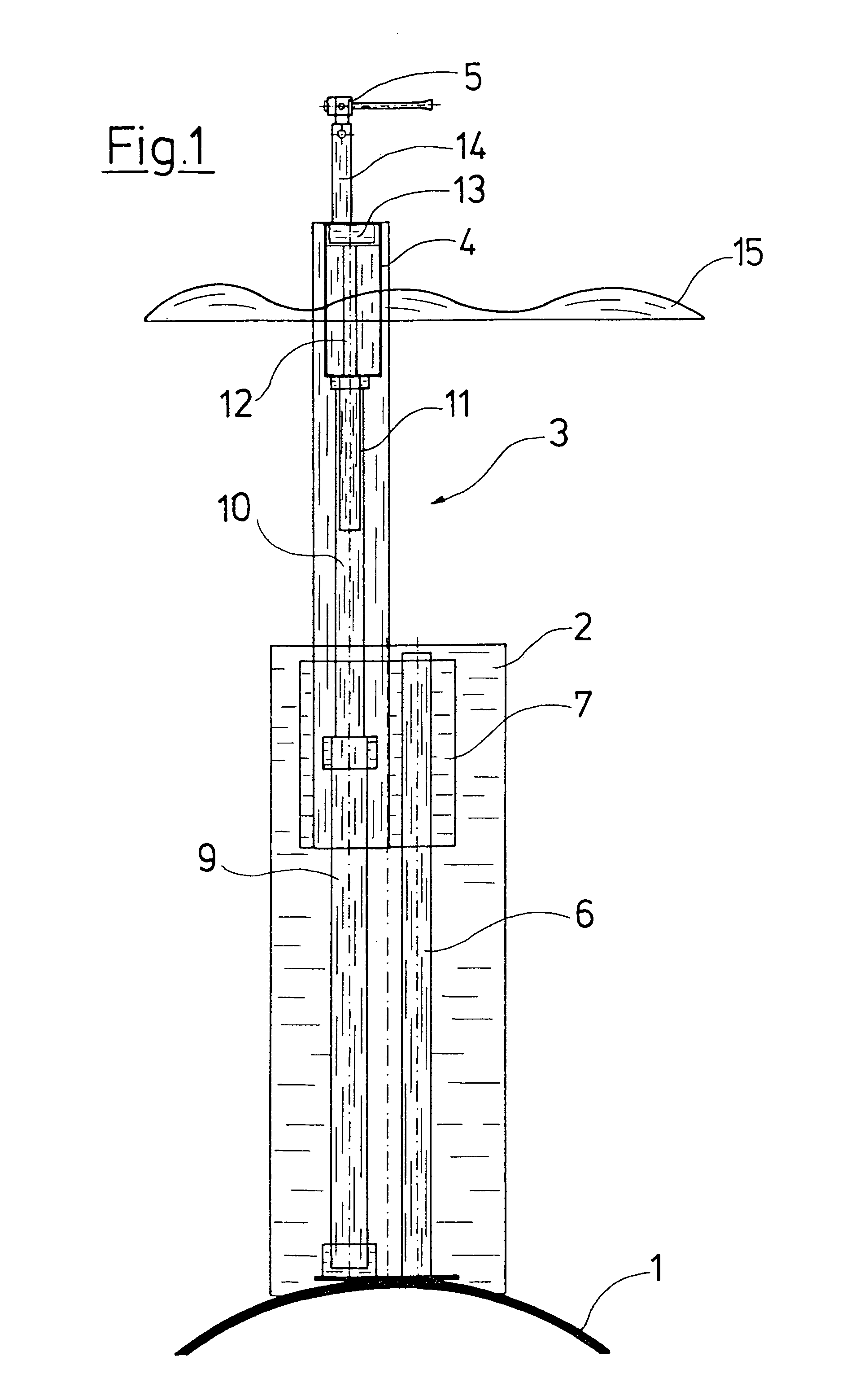
[0023]In FIG. 1 a pressure hull 1 of a submarine known per se is schematically shown in its upper region. In the middle region of this submarine a tower 2 joins this cylindrical pressure hull 1 at the top, in which the access shaft, a snorkel mast, periscopes as well as extending apparatus are arranged in a manner known per se and which are not shown in detail in the figure. The additional extending apparatus 3 according to the invention which carries a container 4 resistant to underwater pressure at it free upper end, in which a machine canon 5 is mounted in an extendable and pivotal manner, is however shown.

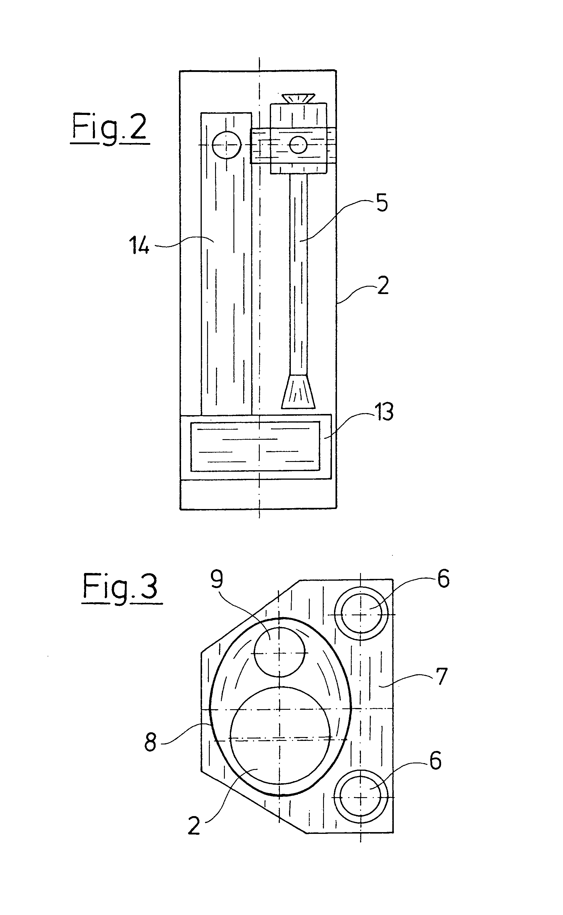
[0024]The extending apparatus 3 is designed as a bridge apparatus, thus is not designed to retract into the pressure hull 1. It comprises two guide profiles 6 which are round in cross section and on which a travel platform 7 is guided in a traveling manner. The travel platform 7 carries a tubular profile section 8 in whose upper end the container 4 is incorporated. The profile ...


PUM


Abstract

A submarine is equipped with an extending apparatus on whose free end a container (4) resistant to underwater pressure is arranged, in which an essentially recoil-free gun (5) lies. The container (4) in the submerged condition of the submarine may be brought to the water surface (15) by way of the extending apparatus, and pivoted out so that one may also shoot in the submerged condition.

Description

CROSS REFERENCE TO RELATED APPLICATIONS[0001]This application claims the benefit of priority under 35 U.S.C. § 119 of German patent application DE 103 30 174.7 filed Jul. 4, 2003 the entire contents of which are incorporated herein by reference.FIELD OF THE INVENTION[0002]The invention relates to submarines, in particular for the military field.BACKGROUND OF THE INVENTION[0003]Submarines of this type usually consist of an essentially cylindrical pressure hull as well as one or more extending apparatus, for example in the form of a periscope, an aerial mast, or likewise which are arranged in the region of the tower and serve for accessing regions above the surface of the water in the submerged condition.[0004]Military submarines are first and foremost designed for combating marine vessels and for this purpose usually comprise torpedoes as weapons. In particular with large, atomic-powered submarines it is counted as belonging to the state of the art to provide so-called launch shafts ...

Claims


Application Information

Patent Timeline
Patent Type & Authority Patents(United States)
IPC IPC(8): F41A23/00B63G1/00B63G8/28B63G8/30F41A1/08F41H11/02
CPCB63G8/30F41H11/02F41A1/08B63G8/28B63G8/38
Inventor SCHARF, WOLFGANGREUTER, JOACHIMKORVER, ROLF
Owner THYSSENKRUPP MARINE SYST GMBH
Why Eureka
Try Eureka