Eureka AIR delivers breakthrough ideas for toughest innovation challenges, trusted by R&D personnel around the world.

Systems and methods for applying texture material to ceiling surfaces

Inactive Publication Date: 2007-10-09
HOMAX PRODS
View PDF69 Cites 43 Cited by
  • Summary
  • Abstract
  • Description
  • Claims
  • Application Information

AI Technical Summary

Problems solved by technology

The formulation of texture material dispensed by conventional aerosol texturing devices may not be appropriate for vertical surfaces.
In particular, the viscosity profile of the conventional texture material may not allow the texture material to be deposited on a ceiling surface without dripping or sagging or in a desired texture pattern.

Method used


Image

  • Systems and methods for applying texture material to ceiling surfaces
  • Systems and methods for applying texture material to ceiling surfaces
  • Systems and methods for applying texture material to ceiling surfaces

Examples


Embodiment Construction

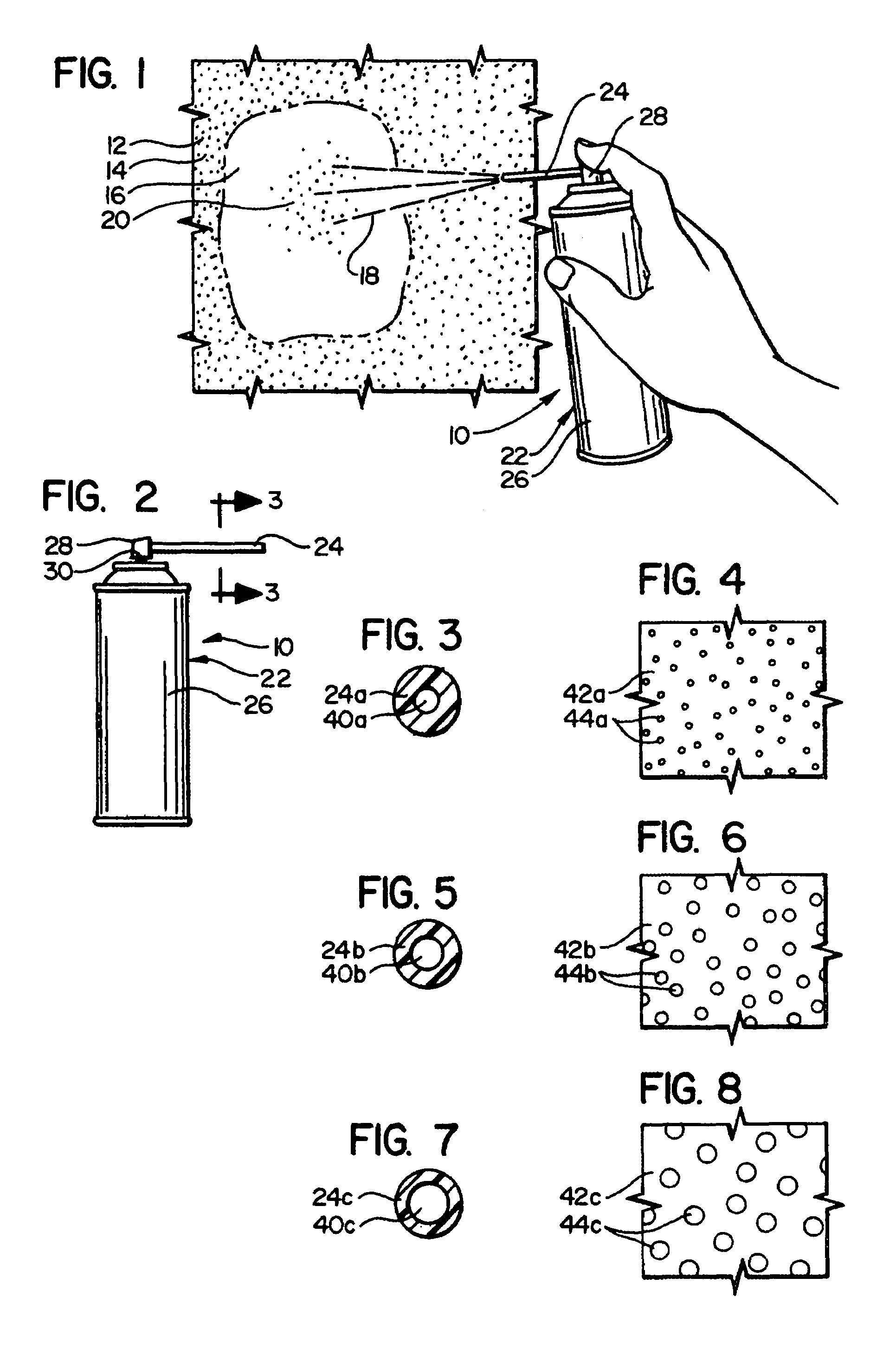
[0108]FIG. 1 depicts and example apparatus or system 10 of the present invention being used in spraying the texture material onto a section of wallboard 12 having a previously sprayed surface portion 14 surrounding an unsprayed portion 16 which could be, for example, a more recently applied piece of wallboard that serves as a “patch”. The spray itself is indicated at 18, and the spray material deposited on the wall portion 16 as a sprayed texture is indicated at 20.

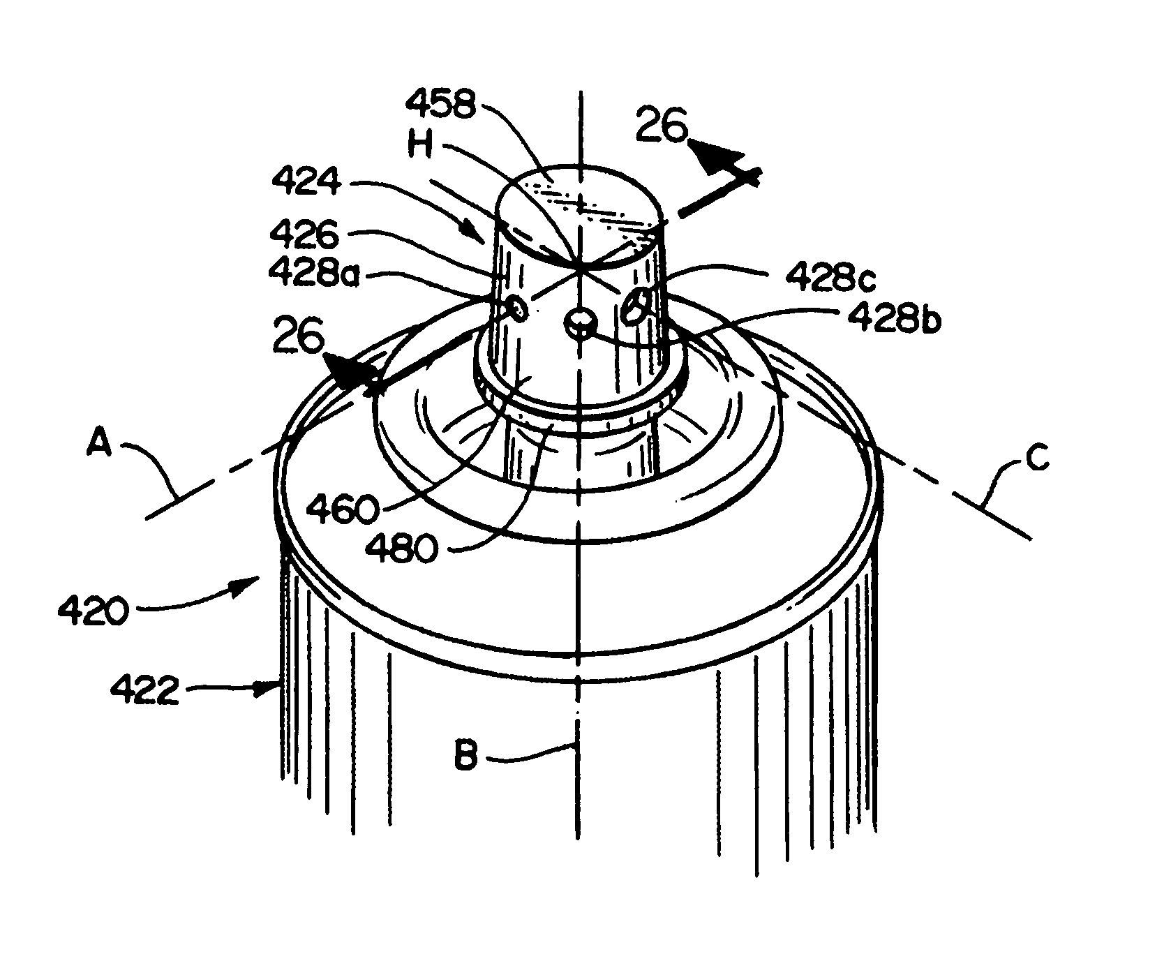
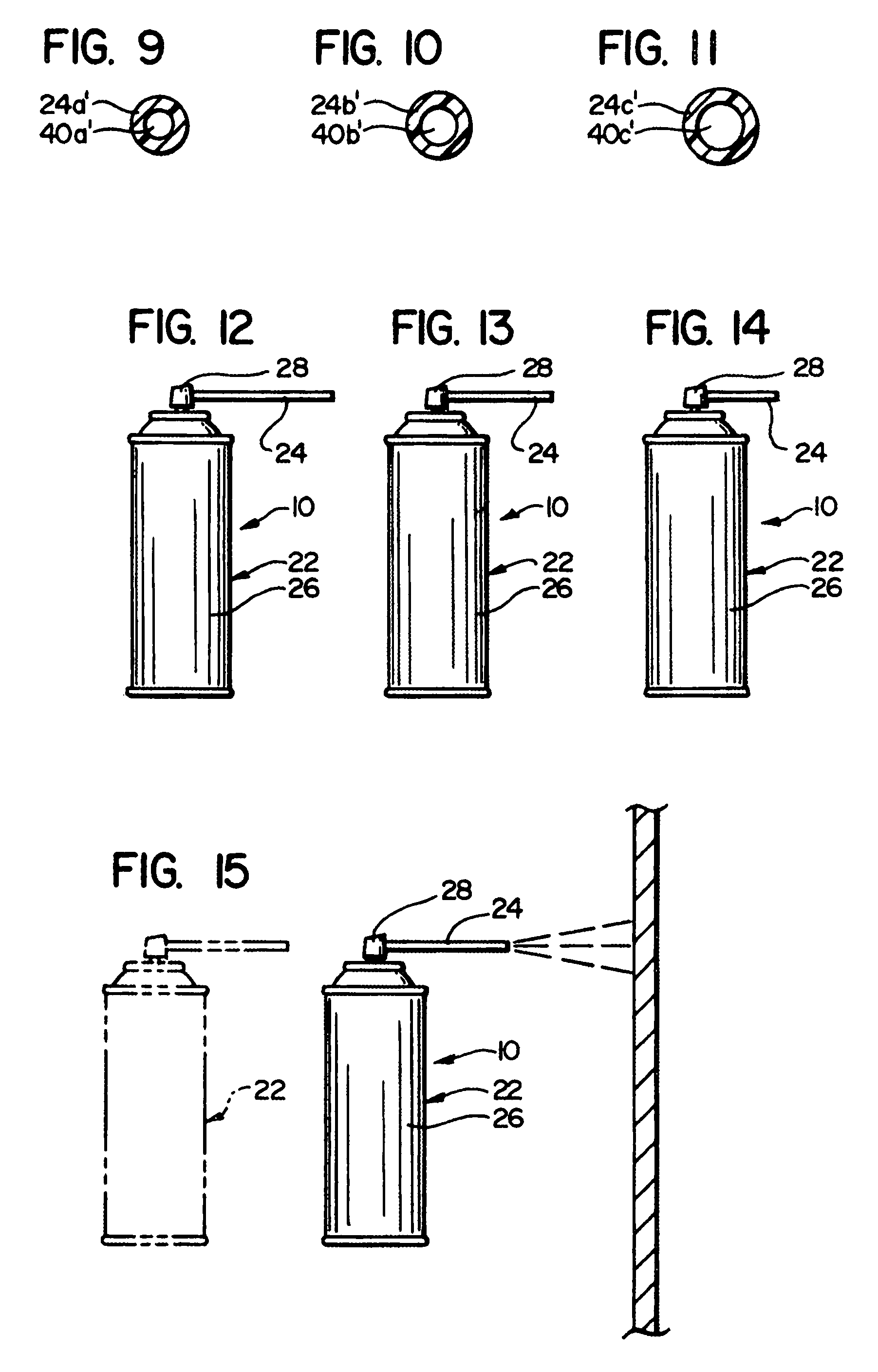
[0109]With reference to FIG. 2, the present invention is shown, in one exemplary form, incorporated with an aerosol spray containing device 22, the basic design of which is or may be conventional in the prior art. Used in combination with this container 22 is a dispensing tube 24. It has been found by utilizing this dispensing tube 24 in particular arrangements to discharge the spray texture material, more precise control of the spray texture pattern can be achieved. Further, there are other advantages, in that not only i...


PUM

PropertyMeasurementUnit
Areaaaaaaaaaaa

Abstract

An aerosol system for dispensing texture material on a horizontal surface comprising an aerosol assembly, an actuator member, and an outlet structure. The aerosol assembly, which is adapted to contain and dispense texture material, defines a container axis that is substantially vertical during normal use. The actuator member comprises a valve stem for engaging the aerosol assembly and defines a first portion of a dispensing path. The outlet structure defines a second portion of the dispensing path, an outlet orifice, and a dispensing axis. The outlet structure is arranged adjacent to the actuator member such that fluid flowing along the first portion of the dispensing path flows through the second portion of the dispensing path and the outlet orifice and generally along the dispensing axis. The dispensing axis is substantially aligned with the container axis. A cross-sectional area of the outlet orifice is adjustable.

Description

RELATED APPLICATIONS[0001]This is a continuation-in-part of U.S. Ser. No. 11 / 102,205 filed Apr. 9, 2005, which is a continuation of U.S. Ser. No. 10 / 396,059 filed Mar. 25, 2003, now U.S. Pat. No. 6,883,688, which is a continuation of U.S. Ser. No. 09 / 989,958 filed Nov. 21, 2001, now U.S. Pat. No. 6,536,633, which is a continuation of U.S. Ser. No. 09 / 458,874 filed Dec. 10, 1999, now U.S. Pat. No. 6,328,185, which is a continuation-in-part of U.S. Ser. No. 09 / 008,524 filed Jan. 16, 1998, now U.S. Pat. No. 6,000,583, which is a continuation of U.S. Ser. No. 08 / 626,834 filed Apr. 2, 1996, now U.S. Pat. No. 5,715,975, which is a continuation-in-part of U.S. Ser. No. 08 / 321,559 filed Oct. 12, 1994, now U.S. Pat. No. 5,524,798, which is a continuation-in-part of U.S. Ser. No. 08 / 238,471 filed May 5, 1994, now U.S. Pat. No. 5,409,148, which is a continuation of U.S. Ser. No. 07 / 840,795 filed Feb. 24, 1992, now U.S. Pat. No. 5,310,095 and a continuation of U.S. Ser. No. 08 / 216,155 filed Mar...

Claims


Application Information

Patent Timeline
IPC IPC(8): B65D83/14
CPCB05B1/02B65D83/7532B05B1/1654B05B1/1663B05B1/30B05B1/32B05B1/34B05B15/066B05B15/068B65D83/306B05D5/00B65D83/207B65D83/30E04F21/12B65D5/00B05D1/12B05D5/02B05B1/1645E04F13/02B05B15/652B05B15/656B05B11/0094
Inventor GREER, JR., LESTER R.STERN, DONALD J.TRYON, JAMES A.
Owner HOMAX PRODS
Why Eureka
Eureka Blog
Learn More