
Fire-control sprinkler system

a sprinkler system and sprinkler technology, applied in the direction of valve operating means/releasing devices, functional valve types, transportation and packaging, etc., can solve the problems of unresolved problems, inefficiency in such a connection, and inefficiency in efficient riser port and component arrangement, so as to improve the connection method, facilitate use, and improve the effect of component connection

Inactive Publication Date: 2003-08-05
FERGUSON FIRE & FAB INC
View PDF3 Cites 57 Cited by
  • Summary
  • Abstract
  • Description
  • Claims
  • Application Information

AI Technical Summary

Benefits of technology

A primary object of the present invention is to fulfill the above-mentioned needs by the provision of a multi-function unitary valve system for providing pressure test, pressure relief, and drain/test fluid flow capability. A further primary object of the present invention is to provide such a system which is efficient, inexpensive, easy to use, as well as overcoming the other above-mentioned problems. Another primary object of the present invention is to fulfill the above-menti

Problems solved by technology

But there are still many unsolved problems, especially for residential uses where the sprinkler system is part of a drinkable water system.
Further, efficient riser port and component arrangements have not achieved their potentials in terms of improved structures, combined purpose lines, or combined purpose components.
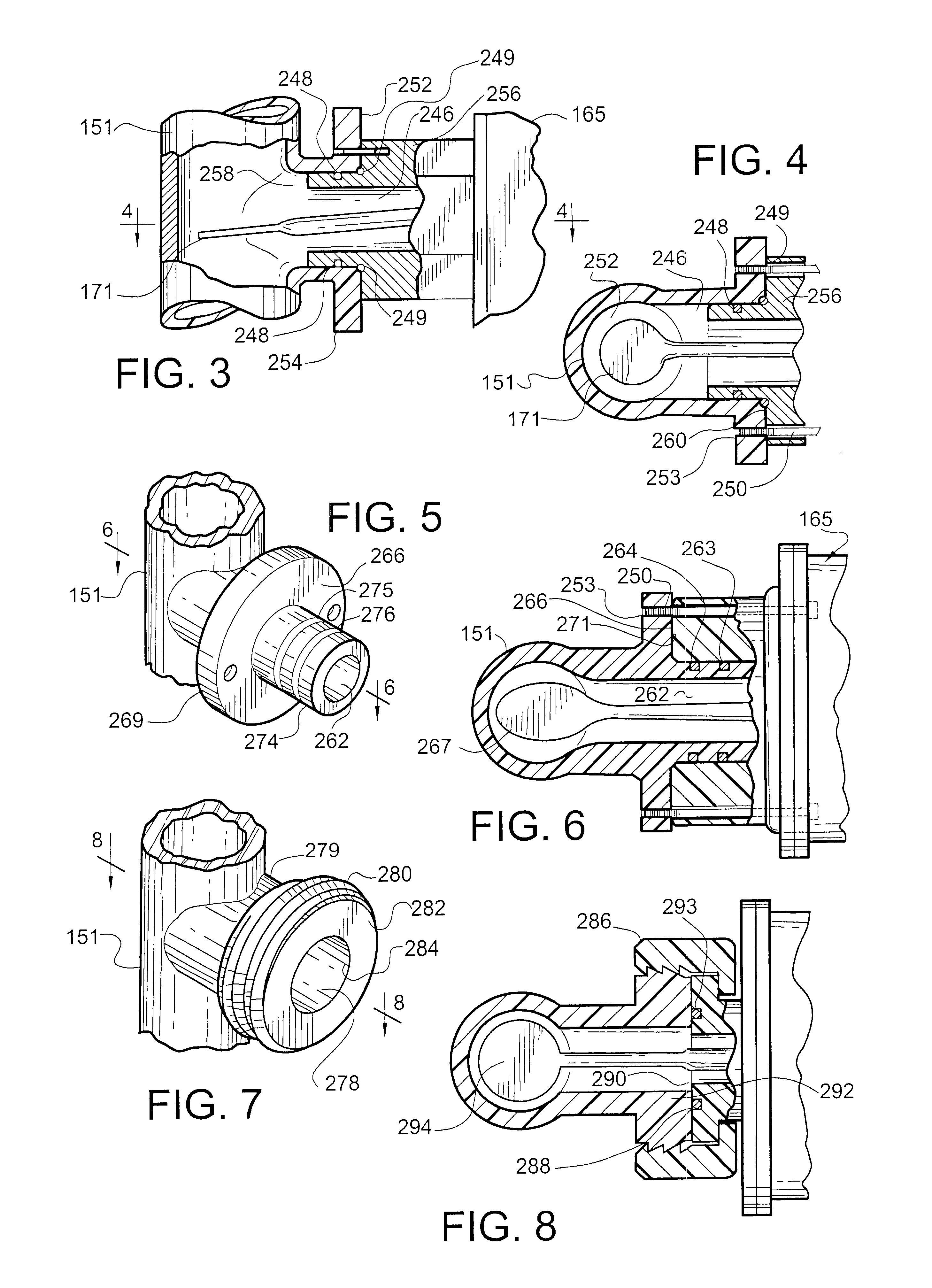
Additionally, flow switches are normally manufactured for connection plumbing by way of pipe threads, usually tapered pipe threads; however, there are many inefficiencies in such a connection.
Thus, a threaded attachment means, utilizing tapered pipe thread, provides a potential point of leakage, additional labor to assemble, unnecessary components and added cost.
Though these multi-valve systems are adequate to perform some of the above-mentioned requirements, they in turn require multiple components and a separate piping system necessitating an increase in expense and space requirements.
However, the elongated handle described therein may be vulnerable to accidental movement.
In addition, the relatively short travel distance along the cammed surface between the open and closed position may result in the "water hammer" effect which arises when a fluid flow through a piping system is suddenly terminated, thereby creating a reverberating pressure wave.
And, in addition to other disadvantages, current such valves do not provide a means to insulate the spring from the system fluid.

Method used


Image

  • Fire-control sprinkler system
  • Fire-control sprinkler system
  • Fire-control sprinkler system

Examples


Embodiment Construction

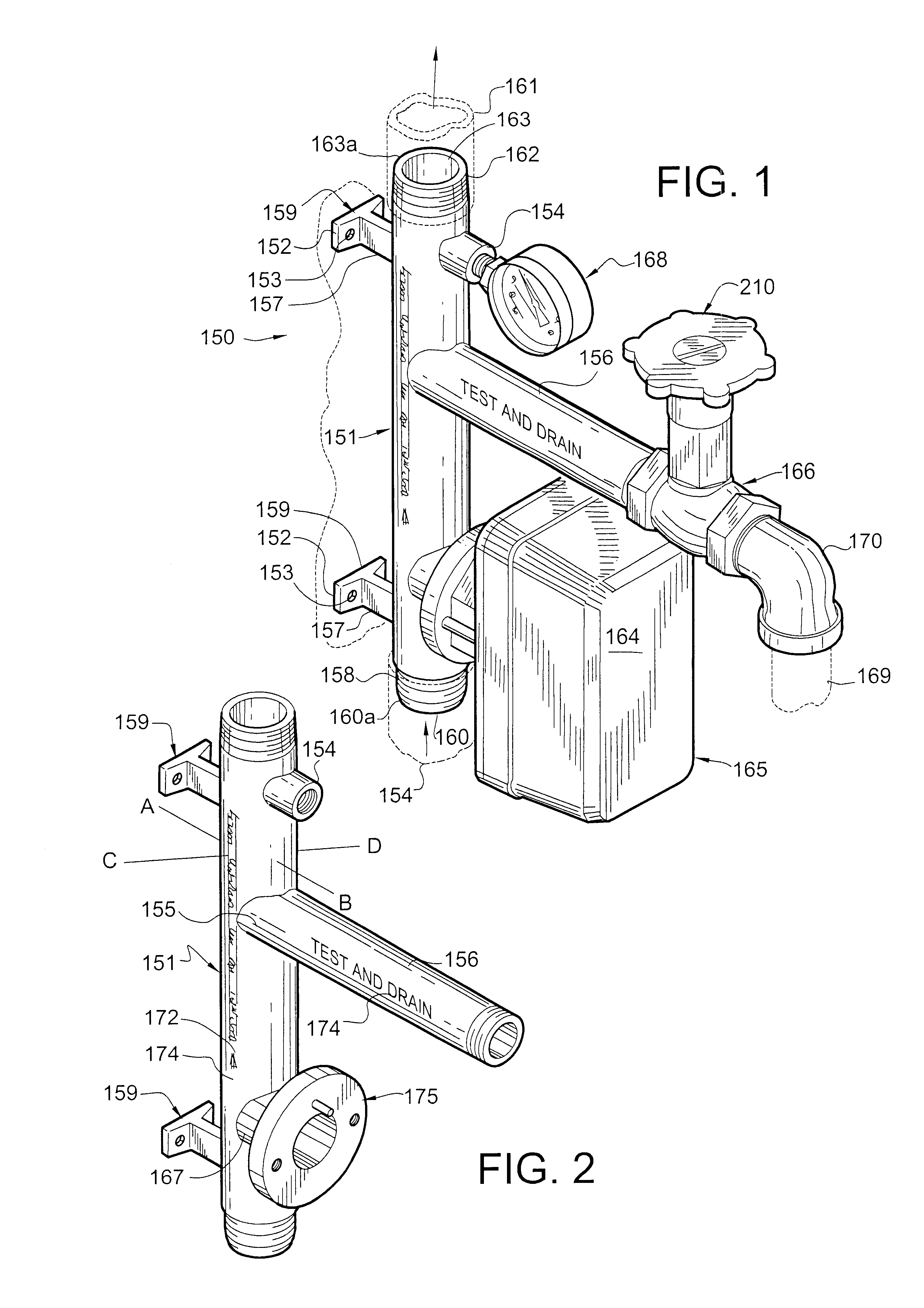
Shown in FIG. 1 is a perspective view of a preferred embodiment of the sprinkler system riser unit of the present invention illustrated as preferably connected (with attached components) in a residential structure; and FIG. 2 is a perspective view of a preferred embodiment of the sprinkler system riser manifold only. With particular reference to FIG. 1, the riser unit 150 is preferably a component of a water sprinkler system for a residential fire protection system. The riser unit 150 includes components used for monitoring delivery of water to the sprinklers, monitoring water pressure, providing system over-pressure relief, and testing and draining the water sprinkler system. Riser unit 150 incorporates a riser manifold unitary means embodied by the one-piece manifold 151 to assist in making connections to the above-mentioned components as well as water system connections, all as hereinafter described.

Manifold 151 incorporates support means (for assisting attachment of the riser ma...


PUM


Abstract

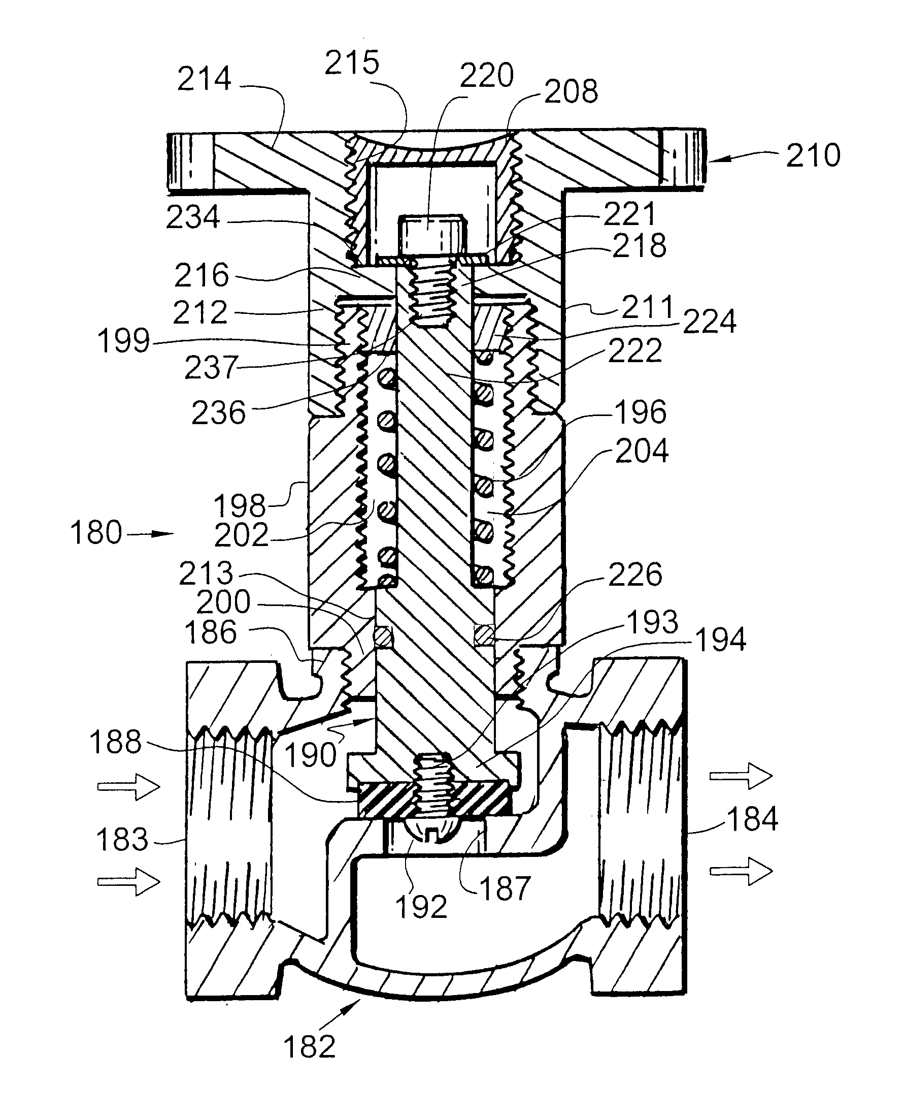
This invention provides for a valve system for use in fire suppression systems that provides pressure relief, pressure testing, and drain / test fluid flow capability. The valve system consists of a valve body with an attached riser. Adjustably attached to the riser is a rotary handle for raising and lowering a spring loaded valve stem. A blocking plug is provided for attachment to the handle which operates to block the movement of the valve stem during pressure testing of the fire suppression system. A tension disk is adjustably attached to the inside of the riser to manually adjust the spring tension. In addition, a means is provided for preventing system fluid from contacting the spring.

Description

Typically, commercial buildings and an increasing number of residential structures are provided with fire suppression systems which dispense a fire suppression medium in the event of a fire. These fire sprinkler systems typically have a central pipe conduit from which a labyrinth of individual piping systems containing a fire suppression medium under pressure are attached. In the event of a fire, sensors which are attached to the individual piping systems are activated thereby releasing the pressurized fire suppression medium in the hopes of quenching the fire. In many instances, the sudden release of system pressure activates a silent and / or audible alarm which alerts both those persons which are on the premises and the local fire authority that a fire is in progress.Since typical fire suppression systems contain fluids under pressure, some means are needed to both check the integrity of the system against leakage and to provide for a means to alleviate system excess pressure in or...

Claims


Application Information

Patent Timeline
IPC IPC(8): A62C37/00A62C37/50F16K31/44F16K31/50F16K15/18F16K15/00
CPCA62C37/50F16K15/18F16K31/504Y10T137/85938Y10T137/5109Y10T137/698
Inventor COOPER, MICHAEL S.
Owner FERGUSON FIRE & FAB INC
Learn More