
In-can fuel cell metering valve

a fuel cell and valve body technology, applied in the direction of liquid transfer devices, manufacturing tools, container discharging methods, etc., can solve the problems of multiple leakage opportunities, reduced fuel cell performance, and certain amount of leakage over time, so as to prolong the operational life of the fuel cell, increase the sealing action, and ensure the effect of sealing

Active Publication Date: 2008-07-01
ILLINOIS TOOL WORKS INC
View PDF36 Cites 56 Cited by
  • Summary
  • Abstract
  • Description
  • Claims
  • Application Information

AI Technical Summary

Benefits of technology

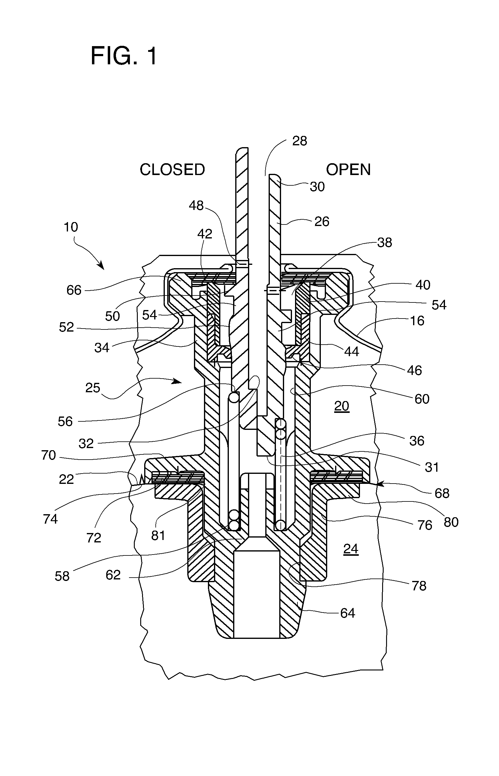
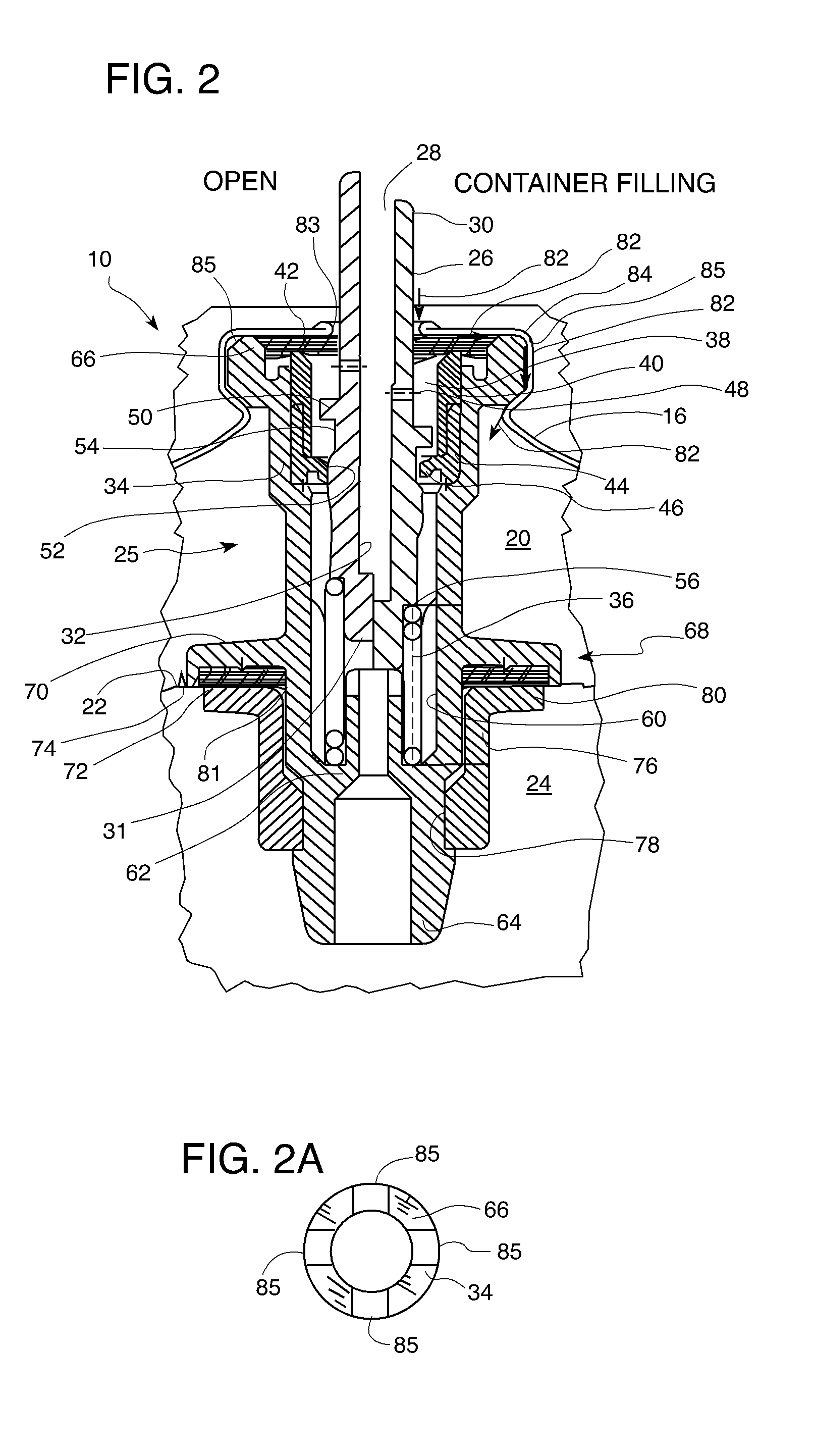
The present invention is a fuel cell metering valve for a combustion tool that features a valve internally mounted in the fuel cell. This valve dispenses a metered amount of fuel with every actuation of the stem and has three positions, closed, open, and container fill. The valve is closed for a large part of its operational life, increasing the sealing action and prolonging the operational life of the fuel cell due to reduced leakage. The valve is provided with a one-piece valve body, one end of which is located inside the inner fuel container located within the fuel cell. This design combines in a single unit the functions of the former standard fuel cell check valve and a supplemental metering valve typically mounted outside of the fuel cell and configured for receiving the valve stem. The present device is more user friendly, easier to install into a fastener driving tool, and reduces the number of components, improving reliability and reducing the cost of the system.

Problems solved by technology

As with other aerosol containers, a certain amount of leakage occurs over time.
However, in the environment of combustion powered fastener driving tools, there is a concern that gradual leakage over a prolonged shelf life may result in reduced performance of the fuel cell due to insufficient propellant and / or fuel.
In the case of internal tool fuel metering valves, an excessive number of seal locations inherently create multiple opportunities for leaks.
However, the aggressive nature of the fuel constituents in some cases cause premature failure of the valve seals or the valve housing itself.
It is thus difficult for the end user to discover and / or prevent fuel leakage due to improper installation of, or internal defects in, the metering valve.
In this position, the seal is relaxed and provides less effective sealing.
As such, there is a greater potential for fuel leakage from the fuel cell.

Method used


Image

  • In-can fuel cell metering valve
  • In-can fuel cell metering valve
  • In-can fuel cell metering valve

Examples


Embodiment Construction

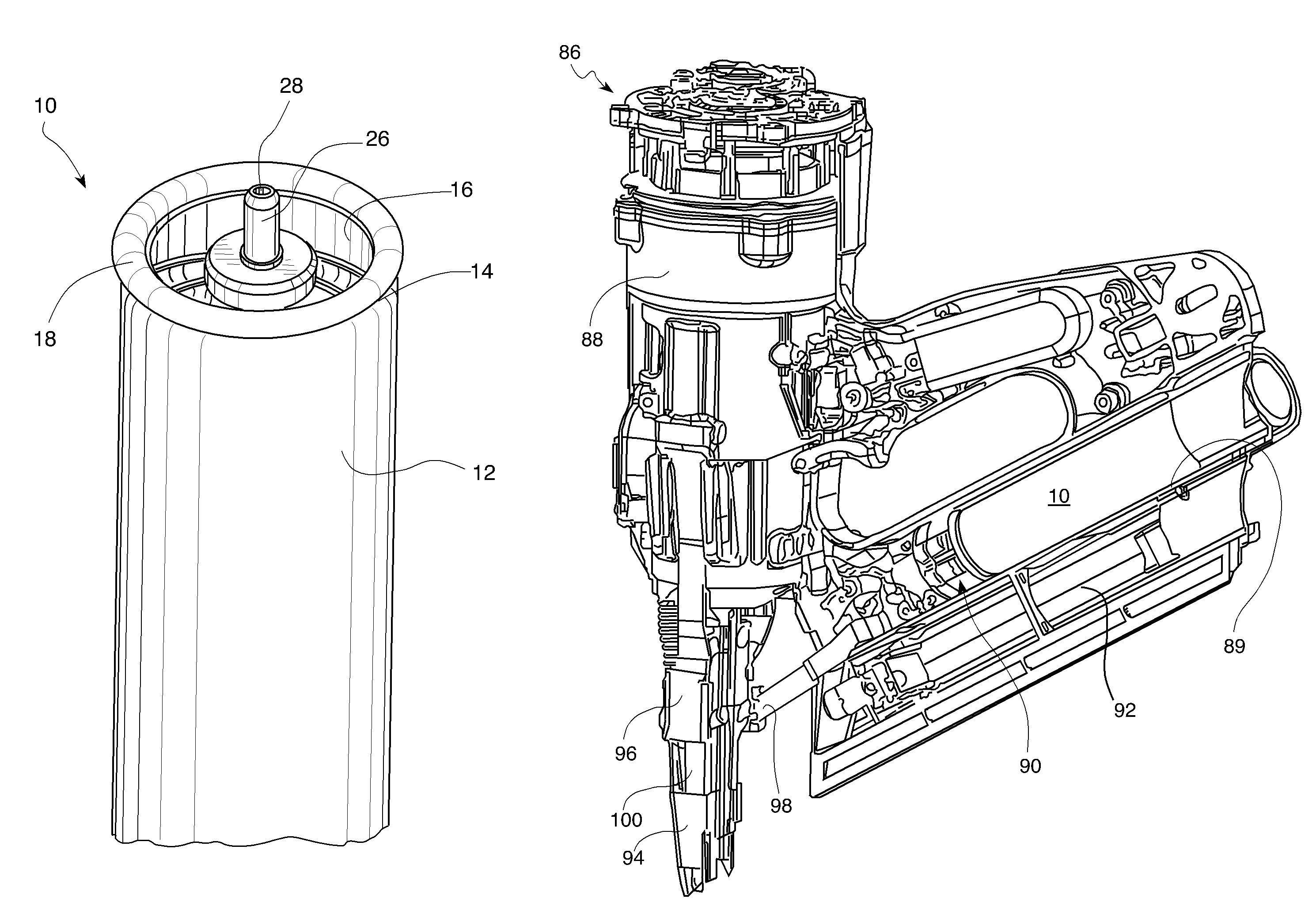
[0019]Referring now to FIGS. 1-4, a fuel cell of the type used in a combustion tool is generally designated 10, and includes an outer housing or shell 12 (seen in FIG. 3) defining an open upper end 14 (FIG. 3) enclosed by a closure 16 which is sealingly secured to the housing at a peripheral edge 18 which overlaps and is preferably crimped over the upper end, as is well known in the art. The general construction of such fuel cells is disclosed in U.S. Pat. No. 5,115,944, incorporated by reference herein. Inside the housing 12, a first space 20 is defined for a first component, which is typically a pressurized propellant. Also provided within the housing 12 is a bag-like container 22 defining a second space 24 for a second component, typically a combustible fuel, usually a liquefied hydrocarbon, either alone or mixed with other compounds. While it is preferred that the first space 20 encloses the propellant and the second space 24 the fuel, other arrangements are contemplated as long...


PUM

PropertyMeasurementUnit
diameteraaaaaaaaaa
volumeaaaaaaaaaa
flexibleaaaaaaaaaa

Abstract

A fuel cell for use with a combustion tool for delivery of a predetermined amount of fuel with each stem actuation is provided and includes a housing defining an open end enclosed by a closure. A main valve stem has an outlet, disposed in operational relationship to the open end and reciprocating relative to the housing at least between a closed position wherein the stem is relatively extended, and an open position wherein the stem is relatively retracted. A fuel metering valve is located within the housing, associated with the main valve stem, including a fuel metering chamber disposed in close proximity to the closure and configured so that when the stem is in the open position, only a measured amount of fuel is dispensed through the outlet. In a preferred embodiment, the fuel cell housing includes a separate fuel container, and the fuel metering valve includes a valve body having a second end opposite the fuel metering chamber located within the container.

Description

BACKGROUND OF THE INVENTION[0001]This invention relates generally to improvements in fuel cell fuel delivery arrangements for use in combustion tools, and more specifically to metering valves used with such fuel cells for delivering the appropriate amount of fuel for use by a combustion tool during the driving of fasteners. While the present application is focused on the use of fuel cells in combustion tools, it is contemplated that other applications are contemplated in which fuel cells or other pressurized containers using stem valves are employed, such as, but not limited to cosmetics and pharmaceutical products.[0002]As exemplified in Nikolich U.S. Pat. Nos. 4,403,722, 4,483,474, 4,522,162, and 5,115,944, all of which are incorporated by reference, it is known to use a dispenser such as a fuel cell to dispense a hydrocarbon fuel to a combustion tool, also known as a combustion gas-powered tool, such as, for example, a combustion gas-powered fastener-driving tool. Such fastener-d...

Claims


Application Information

Patent Timeline
Patent Type & Authority Patents(United States)
IPC IPC(8): B25C1/08G01F11/38B65D83/14B67D7/30F17C13/04
CPCB25C1/08F17C13/04F17C2270/0763F17C2201/0104F17C2201/0119F17C2201/058F17C2203/066F17C2205/0323F17C2205/0335F17C2205/0373F17C2221/032F17C2223/0153F17C2223/033F17C2260/036F17C2270/0545Y02E60/50B65D83/14
Inventor VANSTAAN, VALERY H.WAGDY, MOHAMED K.GEIER, ADALBERTODALSANT, GIUSEPPE
Owner ILLINOIS TOOL WORKS INC
Learn More