Heat dissipating pole illumination device

a technology of illumination device and heat dissipation pole, which is applied in the direction of semiconductor devices for light sources, light and heating apparatus, fixed installations, etc., can solve the problems of reducing the efficiency of energy conversion from power to light, consuming relatively more power, and reducing the service life of heat dissipation device, so as to prevent corrosion, prevent water and insects from forming, and good heat dissipation design

Inactive Publication Date: 2007-10-09
THERMALKING TECH INT
View PDF3 Cites 170 Cited by
  • Summary
  • Abstract
  • Description
  • Claims
  • Application Information

AI Technical Summary

Benefits of technology

[0010]The present invention is to provide an illumination device that has a good heat dissipating design and can keep water and insects off as well as can prevent the occurrence of corrosion.
[0011]Another, the present invention is to provide an illumination device in which heat may be dissipated from its body to the ambient surrounding so as to lengthen its service life.
[0012]Still another, the present invention is to provide an illumination device in which DC from a solar cell and / or a DC power supply unit (which is able to convert AC to DC) may be used so that less power will be consumed.
[0013]The illumination device of the present invention includes a body. The body includes an upper cover, a transparent lower cover, a dividing plate, a power supply unit, a heat dissipating module and a heat conducting plate. A plurality of light emitting units are fitted onto the heat conducting plate. A plurality of venting slots are disposed on each side of the upper cover. The lower cover may engage with the upper cover in a very tight manner. The dividing plate is disposed between the upper cover and the lower cover and can divide the inner space of the body into two parts—a first part and a second part. The second part is fully sealed so as to keep dusts and water off as well as prevent the occurrence of corrosion. The light emitting units are disposed in the second part so as to provide light. The power supply unit is placed in the second part so as to provide power to the light emitting units. The heat dissipating module is disposed in the first part and is connected with the heat conducting plate.
[0014]Hence, heat generated by the light emitting units may be transmitted from the heat conducting plate to the heat dissipating module and then to the venting slots and be dissipated out of the body. Whence, the light emitting units will not be burned out due to excessive heat.

Problems solved by technology

1. Most of them use incandescent bulbs, mercury lights, sodium lights, etc., and hence they have a relatively lower efficiency in terms of the energy conversion from power to light and consume relatively more power. In addition, most of them use only AC and do not use DC or solar cell.
2. A cover is usually used to cover a light. To allow heat to dissipate, such cover is not fully sealed; hence, dusts, sands, water and insects may enter the cover quite easily. These dusts, water and insects soil the inner space of the cover and hence lessen the brightness.
3. No heat dissipating device is disposed in the illumination device. Hence, heat can not be swiftly dissipated and its service life is shortened.
Therefore, we can see that the illumination devices of the prior art have many disadvantages and need to be improved.

Method used


Image

  • Heat dissipating pole illumination device
  • Heat dissipating pole illumination device
  • Heat dissipating pole illumination device

Examples


Embodiment Construction

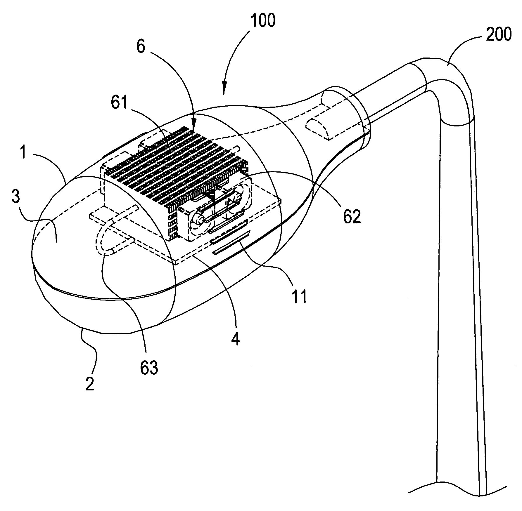
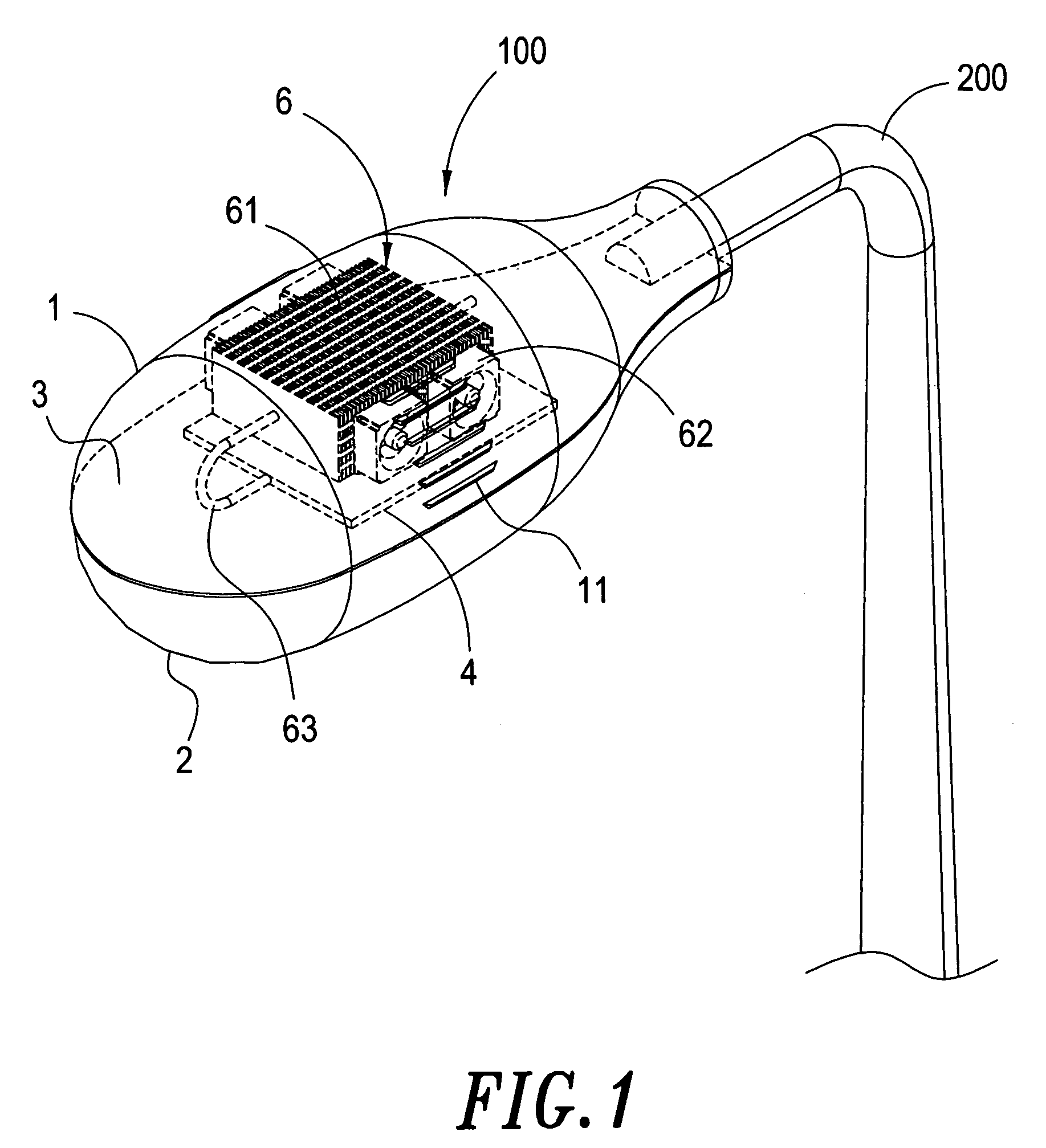
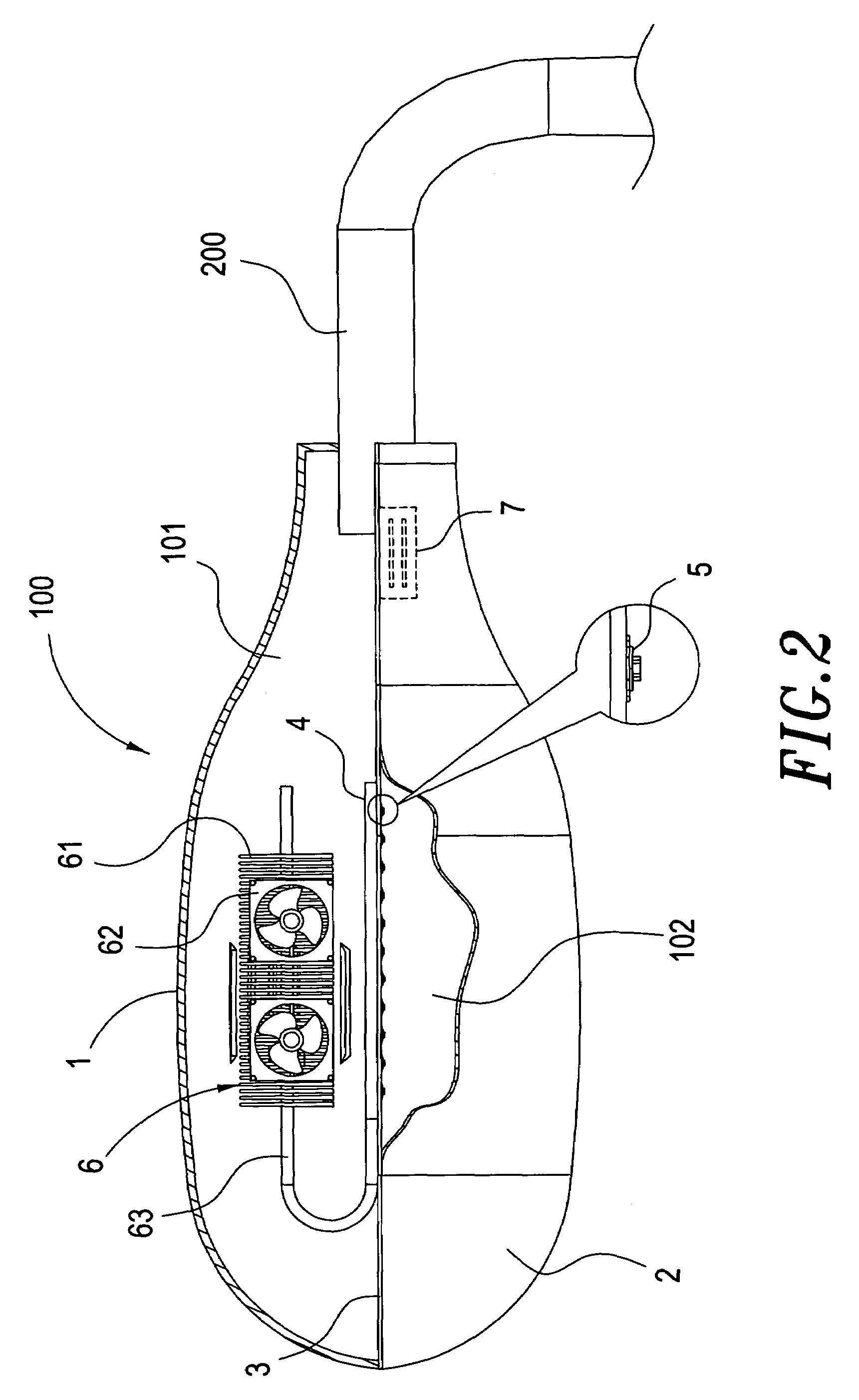
[0023]Referring to FIGS. 1 and 2, an illumination device according to a first embodiment of the present invention is shown. The illumination device is shown as a street lamp. The illumination device comprises a body 100 and a pole 200. The body 100 includes an upper cover 1, a lower cover 2, a dividing plate 3, a heat conducting plate 4, at least a heat dissipating module 6 and a power supply unit 7.

[0024]A plurality of venting slots 11 are disposed on each side of the upper cover 1.

[0025]The lower cover is transparent and may engage with the upper cover 11 in a very tight manner.

[0026]An opening (not shown in the drawings) is provided in the dividing plate 3. The dividing plate 3 is disposed between the upper cover 1 and the lower cover 2 and can divide the inner space of the body 100 into two parts (a first part 101 and a second part 102); these two parts may be an upper part and a lower part or a front part and a rear part or a left part and a right part.

[0027]A plurality of ligh...


PUM


Abstract

An illumination device includes a body. The inner space of the body is divided into two parts as a first part and a second part. A heat dissipating module is disposed in the first part. The second part is fully sealed so that dusts, water and insects may be kept off. A plurality of light emitting units are disposed in the second part so as to provide light. The light emitting units are connected with the heat dissipating module in the first part. Hence, heat generated by the light emitting units may be dissipated out of the body and so that the illumination device of the present invention may have a longer service life.

Description

BACKGROUND OF THE INVENTION[0001]1. Field of the Invention[0002]The invention generally relates to an illumination device. More particularly, the invention relates to an illumination device of which a body is divided into a first part and a second part, and the second part, where light emitting units are disposed, is fully sealed so that dusts and water may be kept off; a heat dissipating module is disposed in the first part so that heat generated by the light emitting units can be dissipated out of the body so that the illumination device of the present invention will have a longer service life.[0003]2. Description of the Prior Art[0004]Illumination devices, including street lamps, yard lamps and other outdoor illumination devices have been indispensable to ensure the safety of people's homes and to keep thieves away and so that people can see in the night times. However, the conventional illumination devices have the following disadvantages:[0005]1. Most of them use incandescent b...

Claims


Application Information

Patent Timeline
Patent Type & Authority Patents(United States)
IPC IPC(8): F21V29/00
CPCF21S8/086F21V29/02F21V29/70F21Y2101/02F21W2131/103F21Y2115/10F21V29/67F21V29/74
Inventor KUAN, HSIN-NING
Owner THERMALKING TECH INT
Why Eureka
Try Eureka