Golf club striking face

a striking face and golf club technology, applied in golf, golf clubs, sport apparatus, etc., can solve the problems of inability to provide the desired pattern, and inability to achieve the desired pattern

Inactive Publication Date: 2007-10-09
MDW TECH
View PDF78 Cites 52 Cited by
  • Summary
  • Abstract
  • Description
  • Claims
  • Application Information

AI Technical Summary

Problems solved by technology

Sand blasting and similar methods can undesirably create a texture having uneven depth across the striking face.
Casting methods typically require a subsequent polishing step to clean the surface and, therefore, do not always provide the desired pattern.
Stamping and milling precision is limited by the equipment and processes.
Stamping, for example, often results in material spring-back that undesirably reduces the accuracy of the desired surface features.

Method used


Image

  • Golf club striking face
  • Golf club striking face
  • Golf club striking face

Examples


Embodiment Construction

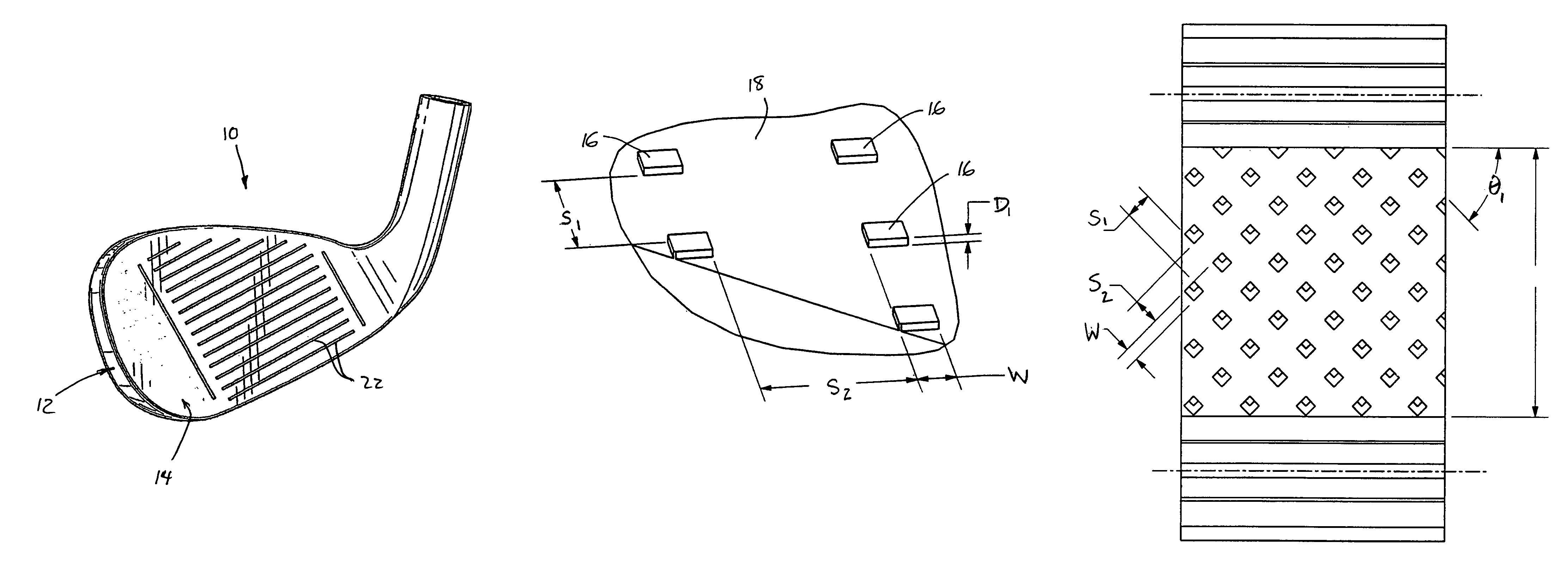
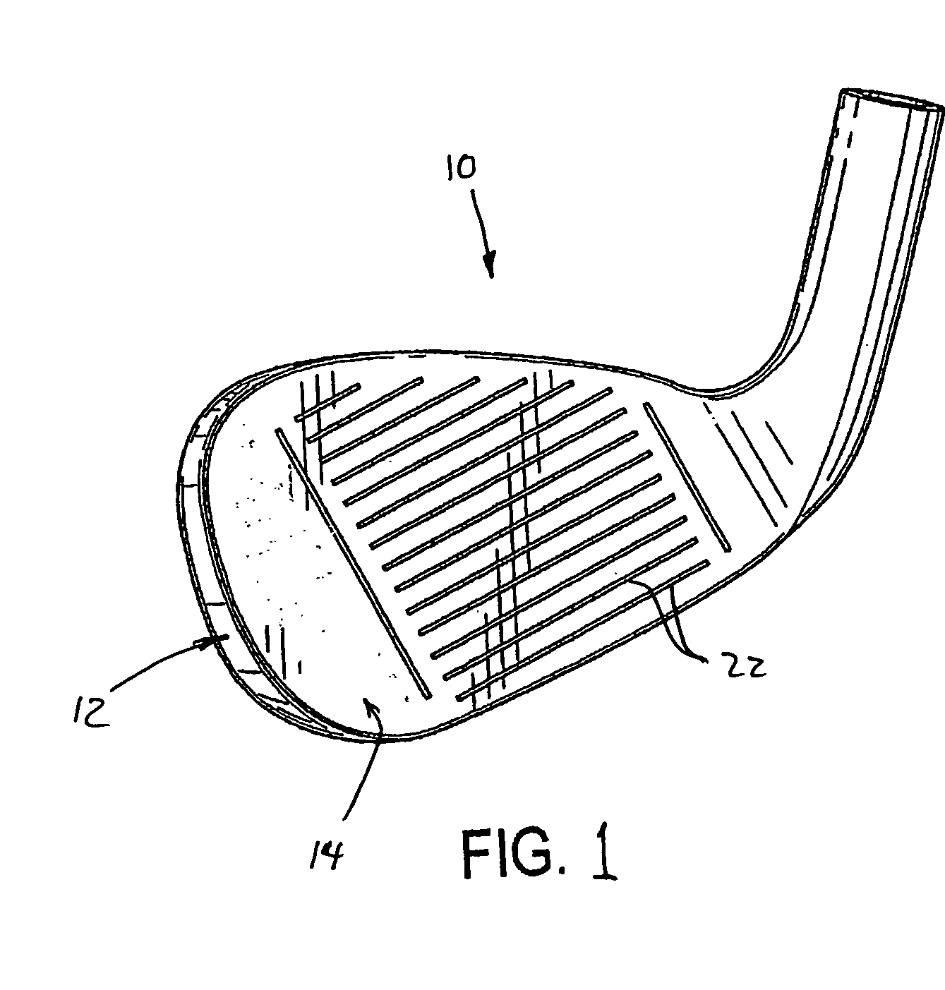
[0025]With reference now to the exemplary drawings, and particularly to FIG. 1, there is shown an iron-type golf club head 10 having a front wall 12 that defines a forward striking surface or face 14. Although the invention has applicability to any kind of golf club, including wood-type clubs, iron-type clubs and putter-type clubs, it has particular advantages for iron-type clubs having loft angles greater than about 45°, i.e., wedges. The front wall preferably is integrally formed with at least a sole portion of a body. Alternatively, the front wall can be a face plate that is separately formed and attached, e.g., by welding, to the front of a club body having a top portion, a toe portion, a heel portion, and a sole portion.

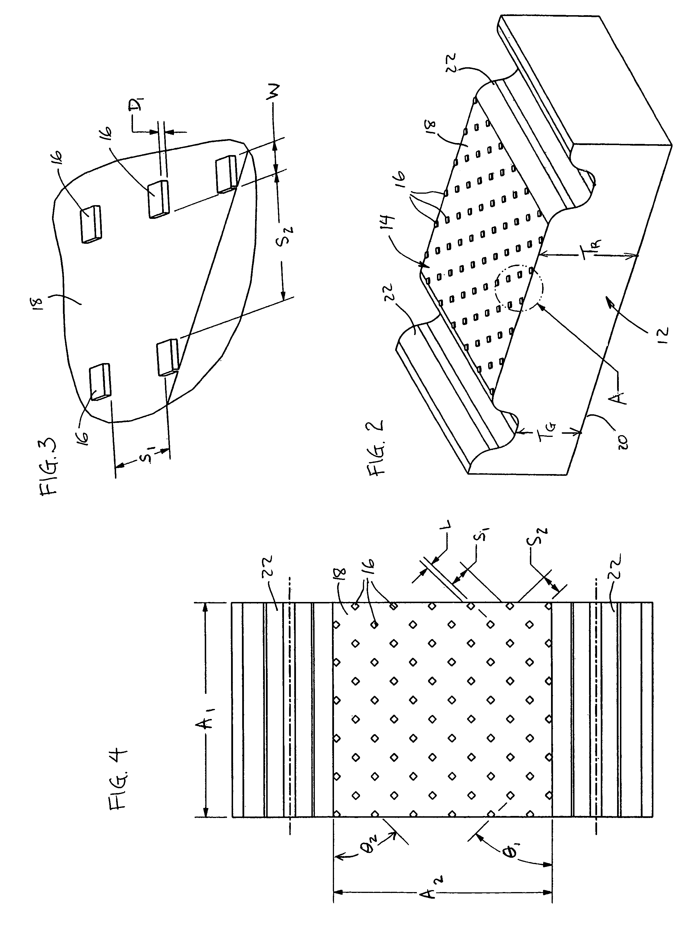
[0026]With reference now to FIGS. 2 and 3, there is shown an engineered texture on the forward striking face 14, for providing enhanced performance upon striking a golf ball (not shown). The engineered texture has the form of a prescribed pattern of discrete, ge...


PUM


Abstract

A golf club head in accordance with the invention includes a forward striking face that comprises a substantially planar recessed surface and a plurality of discrete, solid geometric shapes projecting forward from the recessed surface. Each of the geometric shapes has a volume of less than 0.0007 mm3. The distance along the recessed surface between adjacent shapes is at least 0.1 mm. The total volume of the geometric shapes contained with a square reference region measuring 2.5 mm by 2.5 mm is less than 0.05 mm3.

Description

BACKGROUND OF THE INVENTION[0001]This invention relates generally to golf clubs and, more particularly, to an improved striking face for a golf club head and to a method for manufacturing it.[0002]One of several factors affecting a golfer's ability to obtain the desired distance and accuracy when using a specific golf club is the nature of the contact between the striking face of the club head and the golf ball. Specifically, the type and duration of the contact between the striking face and ball are affected by several factors, including the materials used for the striking face and the ball, and also including the surface geometry of the striking face.[0003]The striking face typically has a surface geometry that includes a groove or scoreline pattern having the form of linear segments and / or indentations. An alternative surface geometry for the striking face is sometimes provided by a media blasting method, e.g., using sand or ceramic glass beads, or by a milling method, in which t...

Claims


Application Information

Patent Timeline
Patent Type & Authority Patents(United States)
IPC IPC(8): A63B53/04
CPCA63B53/047A63B53/0466A63B2053/0479A63B2053/0408A63B2053/0445A63B53/0487A63B53/0408A63B53/0445
Inventor NEWMAN, MARTINFRAME, NICKWAHL, BRETCHAO, BING LINGVINCENT, BENOIT
Owner MDW TECH
Why Eureka
Try Eureka