Core network allocation for GSM/UMTS

a network allocation and core technology, applied in the field of network architecture improvement, can solve the problems of small pockets (such as inside buildings) without umts coverage, inability to expect contiguous coverage of umts radio, and poor penetration of in-building gsm

Inactive Publication Date: 2007-10-09
LUCENT TECH INC
View PDF6 Cites 11 Cited by
  • Summary
  • Abstract
  • Description
  • Claims
  • Application Information

AI Technical Summary

Problems solved by technology

Even within UMTS coverage areas, the UMTS radio coverage cannot be expected to be contiguous.
For example, given that the frequency used for UMTS is higher than that for GSM, the in-building penetration will not be as good as GSM.
This will result in small pockets (such as inside buildings) without UMTS coverage within the overall UMTS coverage area.
If a dual mode mobile terminal communicating via the UMTS radio link goes out of UMTS coverage, to an area with only GSM coverage, it can expect to continue the communication via the GSM radio link, but with a consequential degradation of service.
Changing between two radio access systems involves additional signalling and can also lead to outages during the transition between the two systems.
In addition, if a mobile terminal operating in the 3G mode of operation moves out of 3G coverage, then there is a consequential degradation in service when communication with the 2G core network is established.

Method used


Image

  • Core network allocation for GSM/UMTS
  • Core network allocation for GSM/UMTS
  • Core network allocation for GSM/UMTS

Examples


Embodiment Construction

[0018]The present invention will be described hereinafter by way of reference to the particular non-limiting example of the deployment of a 3rd Generation (3G) mobile system alongside a 2nd Generation (2G) mobile system. In the particular example the 2G system is a GSM / GPRS system, and the 3G system is a UMTS system. The invention, however, is not limited to such a specific environment.

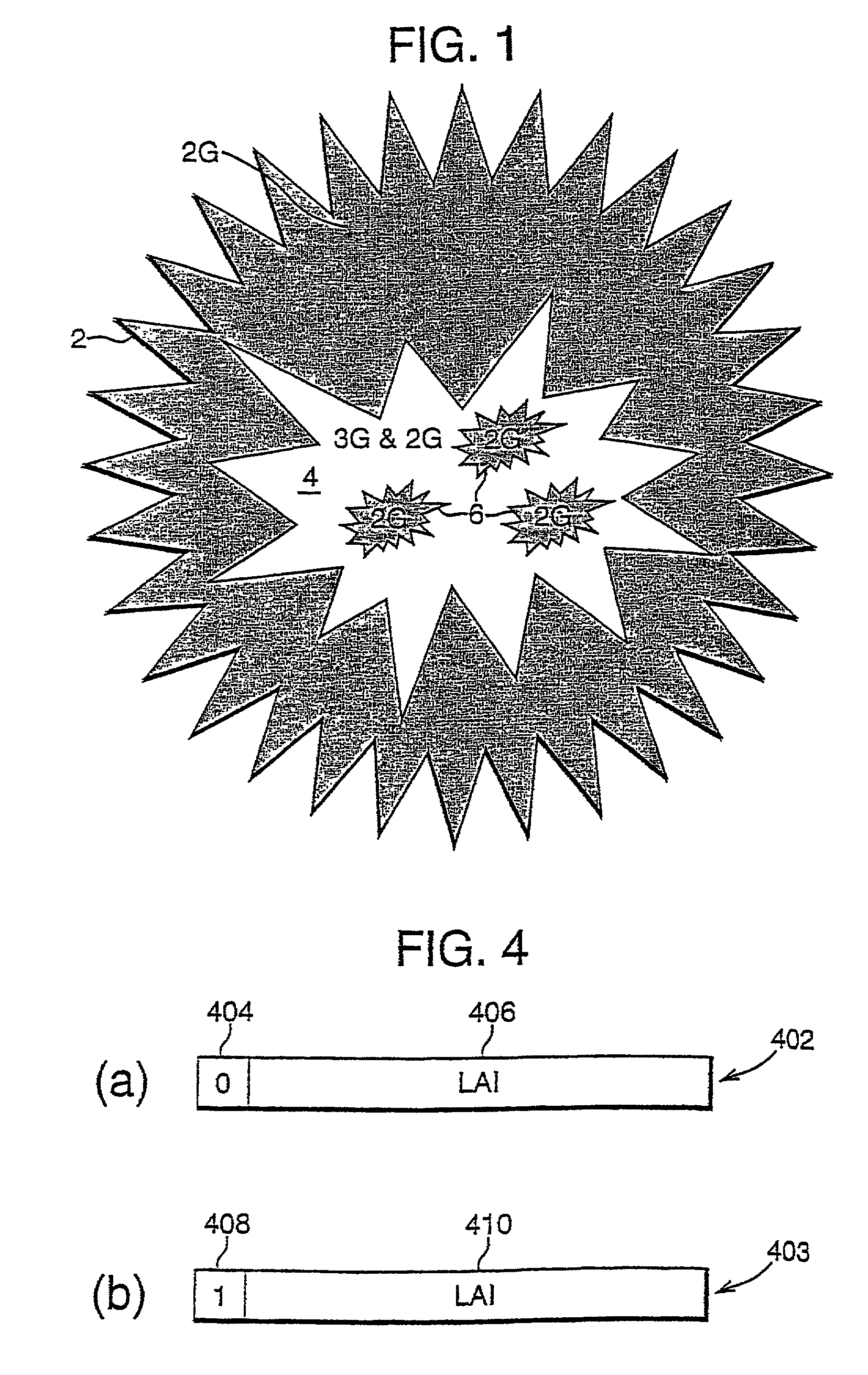
[0019]FIG. 1 illustrates the coverage expected to be provided by UMTS in a GSM radio access area. The shaded areas represent areas with only GSM coverage. The non-shaded areas represent areas with both GSM and UMTS coverage. Thus the whole of the area 2 is provided with GSM coverage. The smaller area 4 within the area 2 is intended to be provided with UMTS coverage in addition to GSM coverage. However pockets, designated by reference numeral 6, exist within the UMTS coverage area 4, such that only GSM coverage is provided in the pockets 6.

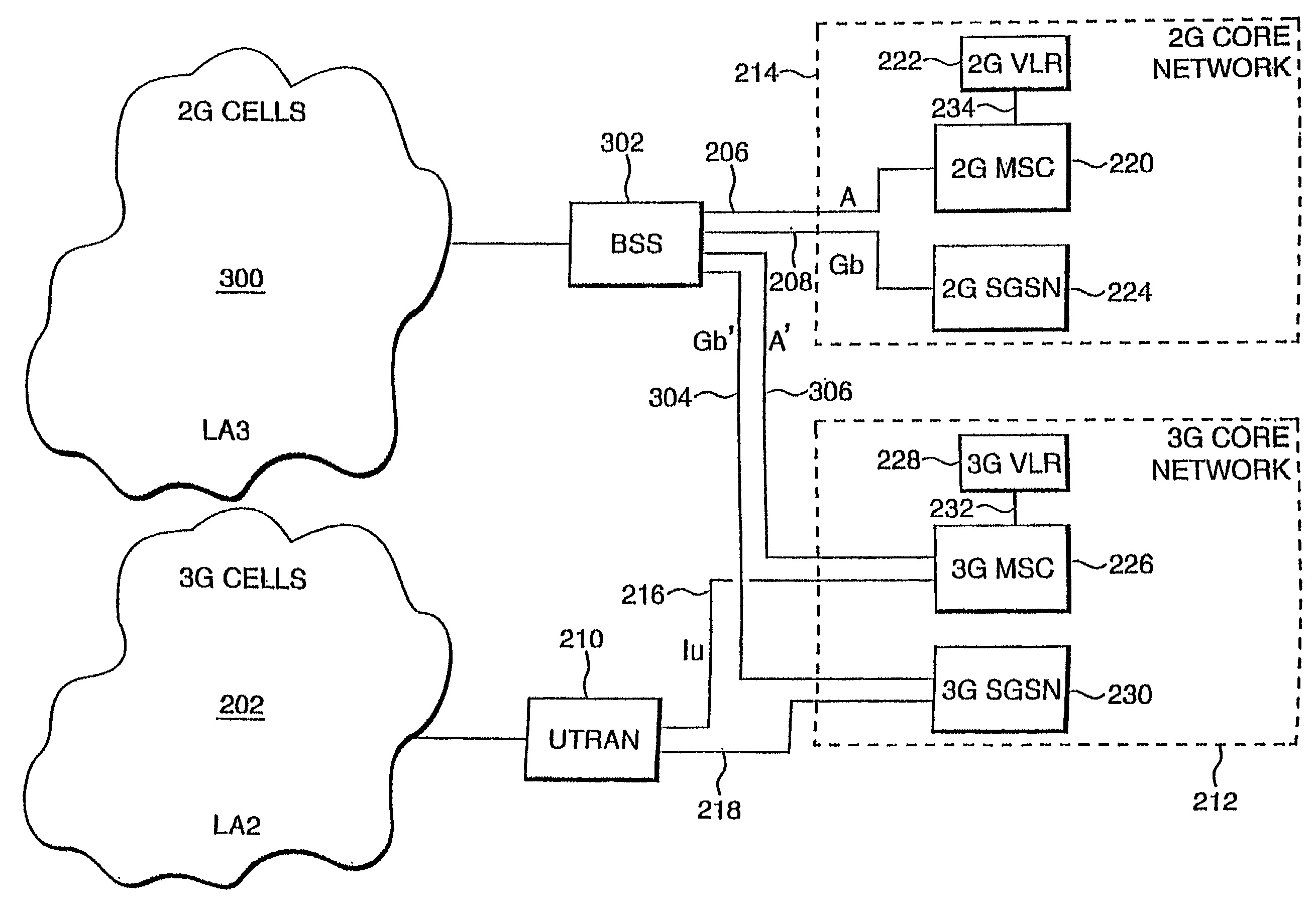
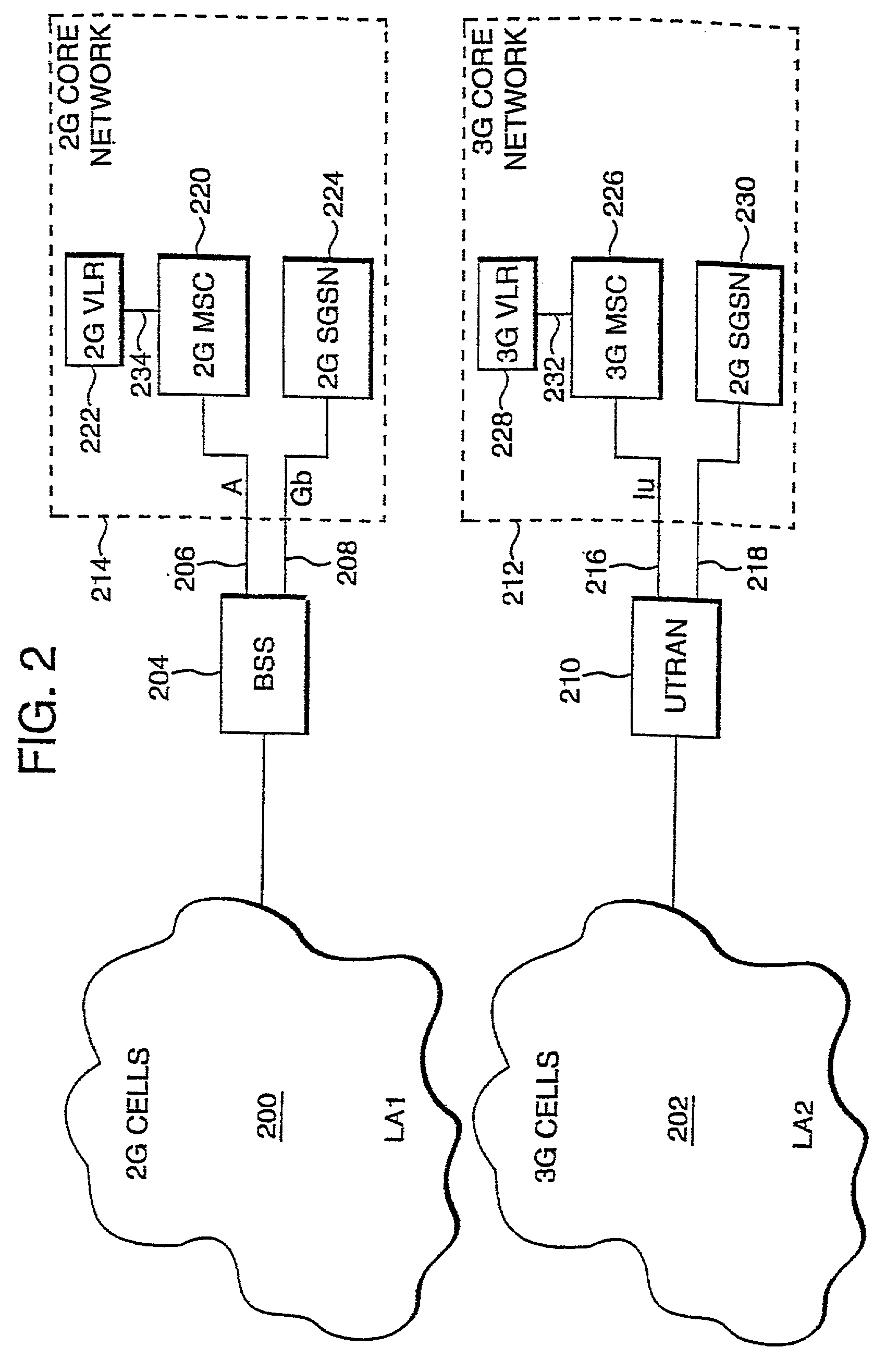
[0020]The current proposed network architecture for supporting ...


PUM


Abstract

A packet switched network architecture comprising a location area connected by a radio access network to at least two core networks having different functionality, wherein the radio access network switches packet transmissions from each terminal in the location area to one of the at least two core networks.

Description

FIELD OF THE INVENTION[0001]The present invention relates to an improved network architecture for an arrangement in which mobile terminals may have at least two functional modes of operation in which the functional modes are provided by at least two core networks having different functionality. The invention is particularly but not exclusively related to the introduction of 3G services into a 2G network architecture.BACKGROUND TO THE INVENTION[0002]GSM (Global System for Mobile Communications) radio coverage, which may also be referred to as second generation (2G) radio coverage, is quite extensive today. During the introduction of UMTS (Universal System for Mobile Telecommunications), which may also be referred to as third generation (3G) radio coverage, UMTS radio coverage is expected to be limited to urban areas. Thus UMTS radio coverage will cover only parts of the more extensive GSM radio coverage areas. Even within UMTS coverage areas, the UMTS radio coverage cannot be expecte...

Claims


Application Information

Patent Timeline
Patent Type & Authority Patents(United States)
IPC IPC(8): H04Q7/24H04Q7/20H04L12/56H04W76/04H04W92/02
CPCH04W48/18H04W28/08H04W92/02H04W36/14
Inventor COSTA, MAUROPALAT, SUDEEP KUMARROBERTS, MICHAELSIVAGNANASUNDARAM, SUTHA
Owner LUCENT TECH INC
Why Eureka
Try Eureka